
How to Choose the Right High-Force Electric Actuator
How to Choose the Right High-Force Electric Actuator—Without Costly Mistakes
Selecting a high-force electric actuator isn’t like picking a standard off-the-shelf component. It’s a mission-critical engineering decision that affects performance, safety, lifecycle cost, and even your product’s market viability. Yet too often, teams focus only on peak force or stroke length—overlooking thermal limits, control compatibility, or mounting dynamics—only to face field failures, redesigns, or safety incidents down the line.
So how do you cut through the noise and choose the right actuator—not just the strongest one? Let’s walk through the real-world selection process, step by step, as practiced by seasoned motion control engineers.
What’s the First Thing You Really Need to Define—Before Looking at Catalogs?
Start with the application profile—not the specs. Force alone is meaningless without context. Ask:
- What type of motion is required? Continuous cycling? Single press? Emergency hold?
- What is the duty cycle? (e.g., 5 seconds on, 55 seconds off = 8.3% duty)
- What environmental conditions exist? Temperature extremes? Washdown? Explosive atmosphere?
- What are the safety requirements? Does it need to hold position during power loss? Is functional safety (PL/SIL) mandated?
These questions shape everything that follows. A 30 kN actuator rated for 100% duty in a cleanroom is useless in a mining shovel that needs 50 kN at 5% duty with IP69K protection and ATEX certification.
Pro Tip: Create a motion profile worksheet that includes:
- Stroke length
- Required speed (extend/retract)
- Peak and continuous force
- Cycle frequency
- Load direction (tension vs. compression)
- Side-load or moment constraints
This becomes your non-negotiable selection filter.
How Do You Translate Real-World Loads Into Accurate Force Requirements?
Don’t just use static weight. Dynamic and resistive forces dominate real applications.
- In compression: Account for buckling risk using Euler’s formula. The critical load
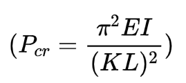 depends on rod modulus (E), moment of inertia (I), effective length (L), and end condition factor (K).
 - In tension: Include inertial forces if accelerating heavy loads
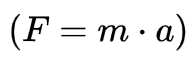 .
. - In pressing or clamping: Add process resistance (e.g., material deformation force, seal friction, spring preload).
- In vertical lifting: Factor in gravity + acceleration + safety margin (typically 1.5–2× working load).
Crucially, distinguish between:
- Peak force (short-duration, e.g., impact or startup)
- Continuous force (sustainable indefinitely without overheating)
Many actuators list only peak force—leading to thermal overload in continuous use. Always verify continuous force vs. duty cycle curves in the datasheet.
Which Screw Mechanism Is Right for Your Application—Ball, Lead, or Roller?
This is the core architectural choice—and it dictates efficiency, speed, force density, and safety.
| Mechanism | Best For | Trade-offs |
|---|---|---|
| Lead (Acme) Screw | Low-speed, self-locking applications (e.g., medical lifts, jacks) | Low efficiency (30–50%), high heat, limited speed |
| Ball Screw | High-speed, high-precision, high-cycle tasks (e.g., CNC presses, automation) | Not self-locking; requires brake for holding; sensitive to contamination |
| Planetary Roller Screw | Extreme force, high shock, long life (e.g., aerospace, forging, defense) | High cost, limited suppliers, complex integration |
Ask:
- Do I need to hold position without power? → Lead screw or add a brake.
- Do I need micron-level repeatability? → Ball or roller screw.
- Is my load >20 kN with high cycling? → Roller screw likely necessary.
Note: Roller screws can deliver 3–5× the force density of ball screws—often allowing a smaller, stiffer package.
How Do You Avoid Thermal Surprises That Kill Performance?
Heat is the silent limiter. A common mistake: assuming a 40 kN actuator can deliver 40 kN continuously.
Instead:
- Calculate RMS (Root Mean Square) force over your full motion cycle:
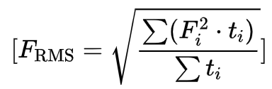 This gives the thermally equivalent continuous load.
 - Compare ( F_{\text{RMS}} ) to the actuator’s continuous force rating at your ambient temperature.
- Check derating curves: A unit rated for 25 kN at 25°C may only handle 18 kN at 50°C.
If your RMS force exceeds the continuous rating, you have three options:
- Reduce cycle time (lower duty)
- Select a larger frame size
- Add active cooling (forced air or liquid)
Ignoring this step is the #1 cause of premature motor burnout.
What Mounting and Load Constraints Are Often Overlooked?
High-force actuators are not structural members. They’re precision thrust devices. Yet misapplication is rampant:
- Side loads >5% of axial load can damage bearings or cause binding.
- Moment loads (from off-center forces) induce uneven nut wear.
- Rod buckling in long-stroke compression applications.
Solutions:
- Use external linear guides (e.g., profiled rails) to carry radial/moment loads.
- Choose dual-rod or guided actuators for inherent anti-rotation and side-load resistance.
- For long strokes under compression, specify a stop tube to reduce effective unsupported length.
- Use spherical rod ends or clevis mounts to accommodate minor misalignment (±2–3°).
Rule of thumb: If your application can’t guarantee perfect axial alignment, assume you need external guidance.
How Do You Ensure Compatibility with Your Control Architecture?
An actuator is only as smart as its integration. Ask:
- What motor type is required? Brushless DC (BLDC), stepper, or AC servo?
- What feedback is needed? Incremental vs. absolute encoder? Resolution (e.g., 17-bit)?
- What communication protocol? Analog (±10V), PWM, or fieldbus (EtherCAT, CANopen, PROFINET)?
- Does it need safe torque off (STO) or dual-channel feedback for functional safety?
Many “integrated” actuators come with built-in drives—but verify:
- Voltage range (24V, 48V, 300V DC bus?)
- Peak vs. continuous current limits
- Regenerative braking capability (critical for vertical or high-inertia loads)
Mismatched control interfaces lead to costly gateways, latency issues, or loss of diagnostic data.
What Environmental and Safety Certifications Are Non-Negotiable?
Don’t treat IP ratings or ATEX as checkboxes—treat them as design constraints.
- IP65: Dust-tight, protected against low-pressure water jets → suitable for factory floors.
- IP67/IP69K: Temporary submersion or high-pressure steam cleaning → food, pharma, agriculture.
- ATEX/IECEx Zone 1/2: Required for oil & gas, chemical plants—demands spark-proof construction and thermal monitoring.
- ISO 13849 PL d/e: Mandates dual-channel monitoring, safe stop, and validated MTTFd for machinery.
These certifications affect material selection (e.g., stainless hardware), seal design, and wiring methods—so involve your safety engineer early.
How Do You Evaluate Total Cost of Ownership—Not Just Upfront Price?
A $2,000 actuator that fails in 6 months costs more than a $5,000 unit lasting 10 years. Consider:
| Cost Factor | Electric Actuator | Hydraulic Alternative |
|---|---|---|
| Energy | 30–70% lower consumption | Continuous pump losses |
| Maintenance | Sealed-for-life; no fluid changes | Filters, seals, oil analysis |
| Downtime | Predictive diagnostics reduce unplanned stops | Leak repairs, contamination events |
| Installation | Single cable (power + data) | Hoses, reservoirs, valves |
| End-of-Life | No hazardous waste | Hydraulic fluid disposal |
Use a TCO (Total Cost of Ownership) model over 5–10 years. In high-cycle applications, electric often pays back in <2 years.
When Should You Engage the Manufacturer—And What Should You Ask?
Don’t wait until you’re comparing PDFs. Involve suppliers early—especially for custom or extreme-duty needs.
Ask:
- “Can you provide FEA validation of buckling and deflection under my load case?”
- “Do you offer thermal modeling for my duty cycle?”
- “What’s your L10 life calculation method (ISO 33001 for roller screws)?”
- “Can you support co-engineering for mounting or integration?”
Reputable manufacturers will provide application engineering support, not just catalogs. For roller screw or custom-force units, lead times can be 12–20 weeks—plan accordingly.
What’s the One Mistake Even Experienced Engineers Make?
Assuming “more force = better.” Oversizing leads to:
- Unnecessary cost and weight
- Poor controllability at low forces (due to coarse screw pitch)
- Higher inertia, reducing system responsiveness
- Excessive heat from oversized motor running below optimal load
Instead, right-size using RMS force, thermal limits, and dynamic requirements. A slightly underspecced actuator with intelligent control often outperforms a brute-force overkill.
Top 10 Brands of High-Force Electric Actuator in Italy
So—How Do You Actually Make the Final Decision?
Follow this selection workflow:
- Define motion & load profile (force, speed, stroke, duty)
- Identify environmental & safety constraints (IP, ATEX, PL)
- Choose screw type based on force, speed, and holding needs
- Calculate RMS force and validate thermal limits
- Verify mounting compatibility (side loads, guidance)
- Confirm control & communication integration
- Compare TCO, not just purchase price
- Engage supplier for validation (FEA, thermal, life)
When done rigorously, this process doesn’t just select an actuator—it de-risks your entire system design.
It’s Not About the Strongest Actuator—It’s About the Smartest Fit
Choosing a high-force electric actuator isn’t a spec-sheet race. It’s a systems engineering exercise that balances physics, environment, control, and economics. The right choice won’t just move your load—it will enhance reliability, reduce lifecycle costs, and future-proof your machine in an era of electrification and intelligence.
And that’s how you turn a component selection into a competitive advantage.