How Is Torque Generated in Electric Actuators?
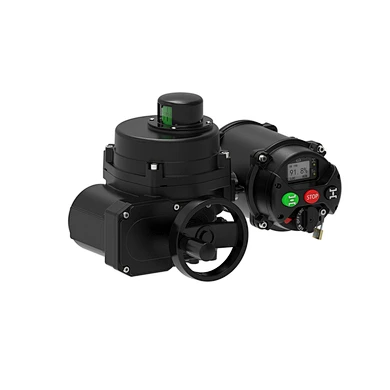
Electric actuators are critical components in modern industrial automation systems — used to control valves, dampers, and machinery with precision and reliability. Unlike their pneumatic counterparts, which rely on compressed air pressure (typically 60–100 psi) to generate motion, electric actuators use torque — the rotational force that enables controlled movement.
For engineers tasked with specifying or upgrading actuation systems, understanding how torque is generated in electric actuators is essential — especially when transitioning from traditional pneumatic setups.
What Exactly Is Torque in an Electric Actuator?
Torque is the twisting force that causes rotation. In rotary electric actuators, it determines how much load the actuator can turn — whether it’s opening a ball valve, adjusting a damper, or rotating a mechanical arm.
It’s typically measured in:
- Newton-meters (Nm) – metric unit
- Pound-inches (lb-in) or pound-feet (lb-ft) – imperial units
Think of torque as the “muscle” behind the motion. Just as low air pressure leads to weak performance in a pneumatic actuator, low torque means your electric actuator may not be strong enough to perform its intended function.
Step-by-Step: How Torque Is Generated
Electric actuators generate torque through a combination of motor power, gear reduction, and electrical input. Let’s break down each stage.
1. The Motor: The Heart of Motion
Every electric actuators starts with an electric motor — usually AC or DC — that converts electrical energy into high-speed rotational motion.
- These motors spin at thousands of RPM but produce relatively low torque.
- Think of it like a sports car engine: fast, but not inherently strong.
Common motor types include:
- Brushed/brushless DC motors
- Stepper motors
- Servo motors
- Three-phase AC induction motors (for heavy-duty applications)
2. Gear Reduction: Trading Speed for Strength
Since the motor spins fast but lacks raw strength, gears are used to slow it down while increasing torque output — just like shifting to a lower gear on a bicycle makes climbing easier.
This process is known as gear reduction, and it’s key to generating usable torque.
Example:
A motor spinning at 3,000 RPM with 5 Nm of torque passes through a 10:1 gear reduction system. The result?
Output speed = 300 RPM
Output torque = 50 Nm (ignoring efficiency losses)
That’s how even a small motor can deliver significant turning force.
3. Voltage and Current: Powering Performance
Just like pneumatic actuators need consistent air pressure, electric actuators require stable voltage and current to maintain optimal torque.
- Low voltage = reduced motor performance = less torque
- High current draw under load = overheating risk = shortened lifespan
Engineers must ensure:
- Voltage matches actuator specifications
- Wiring and circuit protection are adequate
- Power supply is stable and clean
What Influence Electric Actuator Torque Output?
electric actuators are widely used in industrial automation for their precision, reliability, and ease of integration. Unlike pneumatic actuators, which operate within a defined pressure range (typically 60–100 psi), electric actuators rely on torque — the rotational force that enables them to perform work like opening valves or adjusting dampers.
Understanding what affects torque output is crucial when selecting or troubleshooting an actuator. Below are the key factors that influence torque output in electric actuators:
1. Motor Power and Type
The motor is the heart of the actuator and determines how much rotational force it can generate.
Motor Size and Wattage:
- Larger motors with higher wattage typically produce more torque.
- Motors come in various types: brushed DC, brushless DC, stepper motors, and AC induction motors — each with different performance characteristics.
Example:
A 24V DC motor may provide sufficient torque for small ball valves, while a 3-phase AC motor is better suited for high-torque applications like large butterfly valves or industrial gate systems.
2. Gear Reduction Ratio
Gears play a critical role in increasing torque at the expense of speed.
How It Works:
- A gear reduction system reduces the motor’s RPM while multiplying its torque.
- The gear ratio tells you how many revolutions the motor makes per one revolution of the output shaft.
Example:
A gear ratio of 10:1 means:
The motor turns 10 times for every 1 turn of the output shaft
Resulting in 10x more torque (minus efficiency losses)
This allows even small motors to deliver significant force, making gear reduction essential for heavy-duty applications.
3. Voltage and Current Supply
Just like pneumatic actuators depend on consistent air pressure, electric actuators need stable voltage and current to maintain optimal torque.
Voltage:
- Lower-than-rated voltage causes the motor to underperform, reducing available torque.
- Overvoltage can cause overheating and shorten lifespan.
Current:
- Higher loads draw more current.
- Excessive current without proper thermal protection can damage the motor or electronics.
Tip:
Ensure your power supply matches the actuator's specifications and includes overcurrent and thermal protection.
4. Load Conditions and Mechanical Resistance
Torque requirements are directly tied to the mechanical load the actuator must overcome.
Common Load Factors:
- Valve Seat Load: The force required to unseat a valve.
- Backpressure: Fluid pressure inside the line pushing against the valve closure.
- Friction: From seals, bearings, or worn components.
- Inertia: Especially important during acceleration/deceleration in modulating control.
If any of these increase unexpectedly, the actuator must compensate with additional torque — or risk stalling or failing.
5. Actuator Design and Efficiency
Different actuator designs affect how efficiently torque is delivered.
Key Design Considerations:
- Screw Mechanism Type: Ball screws vs. lead screws have different efficiencies.
- Lubrication: Proper lubrication reduces internal friction and extends life.
- Material Quality: High-quality gears and bearings reduce wear and maintain torque output over time.
Poorly designed or low-quality actuators may lose up to 20–30% of torque due to internal inefficiencies.
6. Control System and Feedback Mechanisms
Modern electric actuators often include advanced control features that influence torque delivery.
Features That Impact Torque:
- Soft Start/Stop: Reduces shock loading and protects both the actuator and valve.
- Torque Limiting: Prevents over-tightening or mechanical damage.
- Position Feedback (Encoders/Potentiometers): Ensures accurate positioning and consistent torque application.
- PID Control: In modulating applications, ensures smooth, proportional adjustments based on real-time feedback.
These systems allow for precise torque management, especially in complex automation setups.
Comparing Torque to Pneumatic Pressure
While this article focuses on electric actuators, it’s helpful to compare torque generation with the more familiar concept of air pressure in pneumatic actuators.
| Feature | Pneumatic Actuator | Electric Actuator |
|---|---|---|
| Operating Medium | Compressed Air | Electricity |
| Force Generation | Pressure (psi/bar) | Torque (Nm/lb-in) |
| Standard Operating Range | 60–100 psi (4–7 bar) | Varies by application |
| Control Signal | 3–15 psi (pneumatic signal) | 4–20 mA, Modbus, Digital I/O |
| Precision | Moderate | High |
| Maintenance | Higher (air prep, leaks) | Lower |
| Energy Efficiency | Lower (compressors consume more energy) | Higher |
In essence:
Torque is the electric actuator’s equivalent of pressure. Both define the amount of work the actuator can perform under real-world conditions.
Choosing the Right Torque
Let’s say you're automating a water treatment plant with multiple ball valves. Each valve has different torque requirements based on size, material, and operating pressure.
Here’s a simplified example:
| Valve Size | Minimum Required Torque | Recommended Actuator Torque |
|---|---|---|
| ½ inch | 10 Nm | 15 Nm |
| 1 inch | 30 Nm | 45 Nm |
| 2 inches | 80 Nm | 100 Nm |
| 4 inches | 200 Nm | 250+ Nm |
Adding a 20–30% safety margin ensures reliable operation, even under unexpected load variations.
Why Torque Matters in Engineering Decisions
Selecting an properly sized actuator is crucial for both performance and longevity:
- Undersized Actuator: May stall, overheat, or fail to fully open/close a valve.
- Oversized Actuator: Can cause mechanical stress or damage to the valve stem or sealing surfaces.
Additionally, in modulating applications (where precise positioning is needed), engineers should consider:
- Position feedback via encoders or potentiometers
- Adjustable torque settings
- Soft start/stop features to prevent shock loading
Need Help Selecting the Right Electric Actuator?
At Valen Tech Co., Ltd., we specialize in delivering high-performance electric actuators designed for industrial precision and durability. Our engineering team can help you select the right actuator based on torque requirements, environmental conditions, and control system compatibility.
Explore our product catalog
Contact us for custom solutions
Whether you're working with ball valves, butterfly valves, or complex modulating systems, Valen Tech provides the tools and expertise you can trust.