
Valve Actuator Wiring
author: ATHENA GROUP
2026-10-15
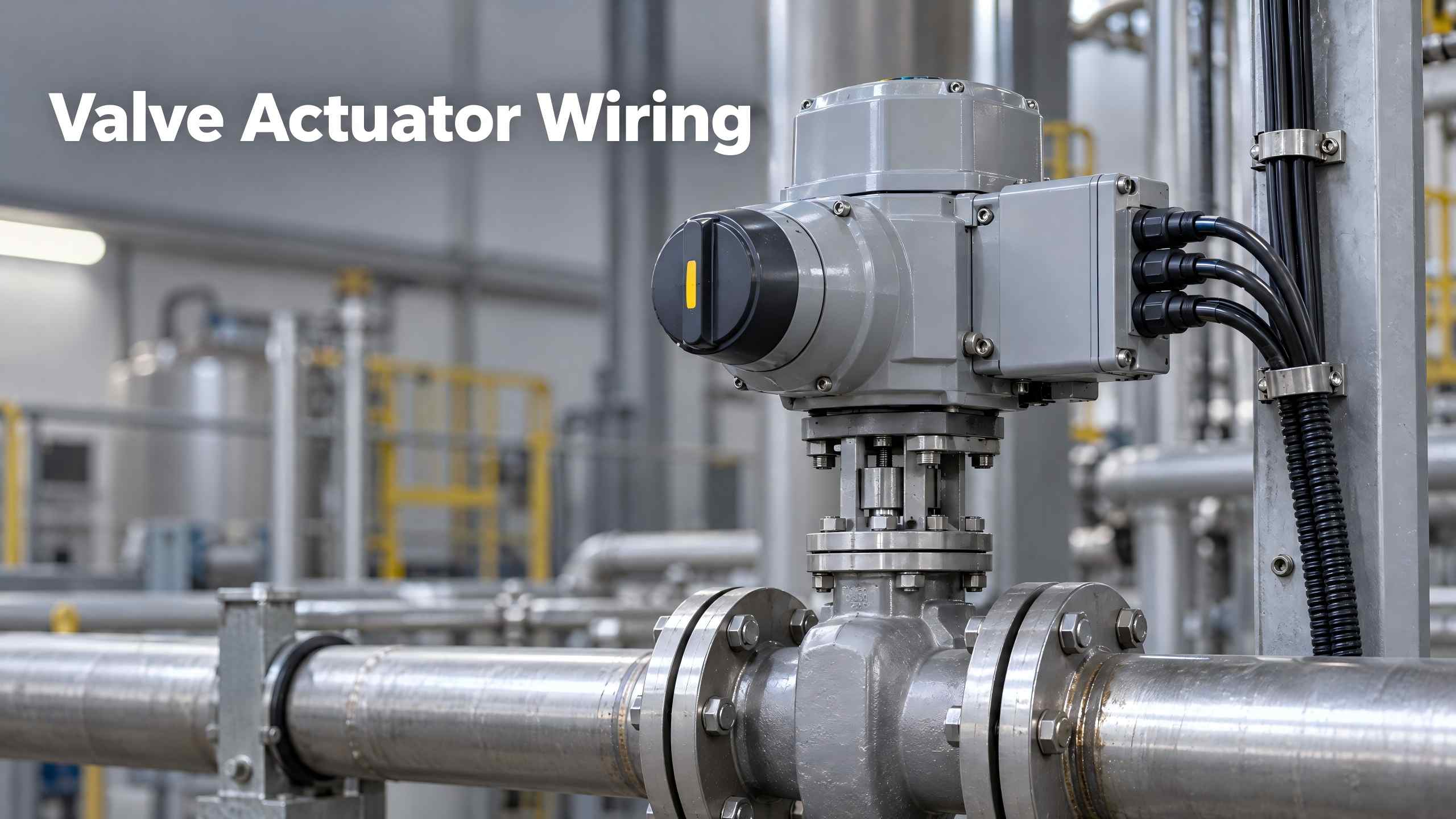
Valen Tech focuses on the R&D and manufacturing of valve actuators. In industrial automation control systems, valve actuator wiring constitutes a critical procedure. Standardized wiring not only ensures stable operation of automatic control systems but also improves regulation accuracy and safeguards on‑site production safety. Improper wiring may result in actuator non‑response, valve jamming and signal loss; in severe cases, it can directly burn out the control mainboard. Targeting instrument engineers, field electricians and engineering technicians in the automation industry, this document sorts out complete wiring procedures, terminal definitions, practical operation essentials and troubleshooting schemes to help operators enhance operational accuracy and work efficiency.
Basic Knowledge of Actuators
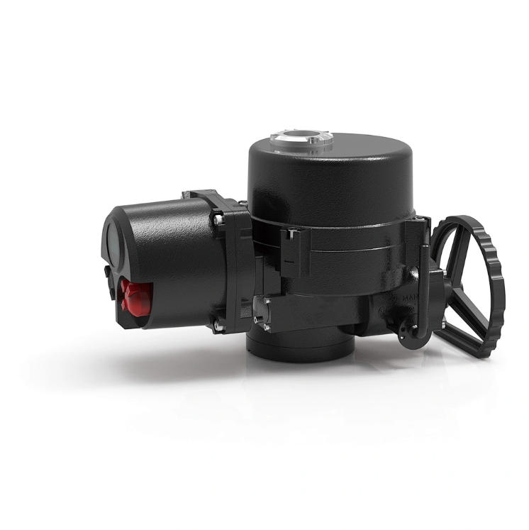
Prior to performing wiring work for valve actuators, it is necessary to get familiar with the basic composition and working principle of electric control valve actuators. An electric control valve actuator generally consists of core components including a drive motor, position feedback device and controller. The actuator receives signals issued by PLC and DCS control systems to drive the valve for opening regulation. Correct wiring serves as a prerequisite for accurate signal transmission as well as the foundation for stable and precise actuator operation. A solid understanding of actuator hardware is essential before carrying out valve actuator wiring.
Pre‑wiring Preparation
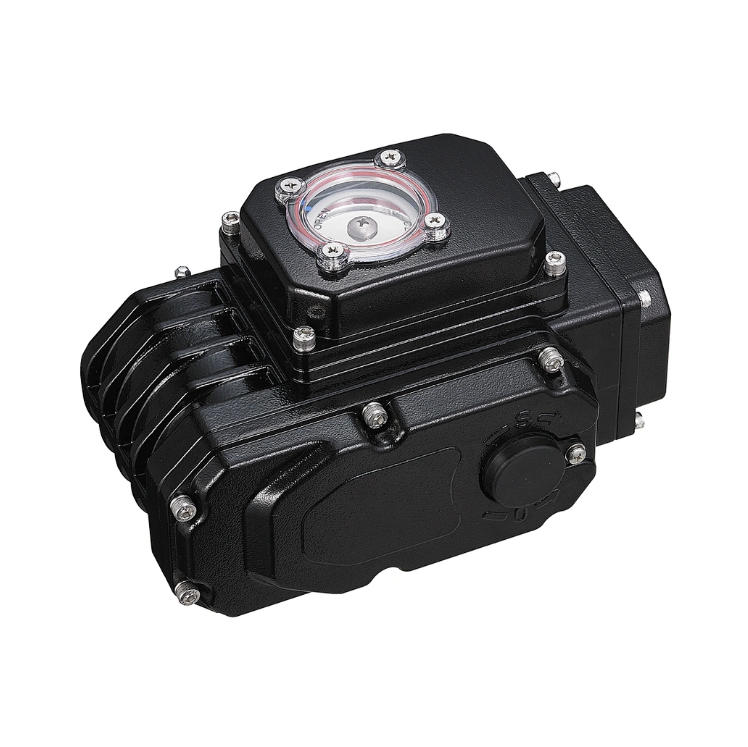
Adequate preparation prior to formal valve actuator wiring cannot be overlooked, which mainly includes the following items:
1. Verify the rated power supply voltage of the actuator and confirm matching between on‑site power supply specifications and equipment parameters;
2. Check whether materials such as cables and wiring terminals are complete and intact;
3. Carefully read the supporting technical manual of the actuator as well as technical manuals and wiring diagrams for the actuator and control system;
4. Cut off equipment power supply and implement lockout‑tagout procedures to prevent accidental power‑on and ensure personal and equipment safety.
2. Check whether materials such as cables and wiring terminals are complete and intact;
3. Carefully read the supporting technical manual of the actuator as well as technical manuals and wiring diagrams for the actuator and control system;
4. Cut off equipment power supply and implement lockout‑tagout procedures to prevent accidental power‑on and ensure personal and equipment safety.
Thorough preliminary preparation can avoid subsequent wiring rework and eliminate potential safety hazards, which is particularly important for reliable valve actuator wiring.
Wiring between Actuator and Control System
Wiring between the actuator and control system represents the core work of valve actuator wiring, which usually involves identification and terminal connection of control signal cables, power cables and feedback signal cables. Each loop is equipped with dedicated wire colours and markings. Construction strictly in accordance with manufacturer‑supplied wiring diagrams is the key to error‑free wiring.
Power Terminal Section
Common power supply specifications include AC 220 V, AC 110 V and DC 24 V. L stands for live wire, N for neutral wire, and PE for protective earth wire. Reliable earthing must be implemented on industrial sites to reduce static interference and prevent electric shock risks; the earth wire must never be omitted.
Regulation Signal Section
Modulating actuators realize continuous regulation via 4‑20 mA or 0‑10 V analogue signals. Connect the positive signal pole to the Signal + terminal and the negative signal pole to the Signal − terminal. Some models are fitted with valve position feedback terminals, which can transmit real‑time valve opening signals back to the control system for closed‑loop monitoring.
Use compatible wiring terminals and connectors during wiring to guarantee firm connections with good contact for all joints. Route cables through cable glands and tighten them to prevent dust and moisture from entering the housing. Power cables and signal cables shall be laid separately instead of being bundled together to reduce electromagnetic interference. Shielded twisted‑pair cables are recommended for 4‑20 mA signal wires, with single‑point earthing for the shielding layer.
Commissioning and Inspection
Completion of valve actuator wiring does not mark the end of the entire installation work. System commissioning is the final step to verify wiring correctness and actuator performance. This phase generally includes continuity testing, feedback signal calibration and dynamic response testing:
1. Perform continuity testing first to troubleshoot open‑circuit and short‑circuit faults;
2. Calibrate valve position feedback signals and confirm whether returned opening data is normal;
3. Conduct dynamic response testing to verify whether the actuator can respond accurately to control signals and feed back correct position information.
2. Calibrate valve position feedback signals and confirm whether returned opening data is normal;
3. Conduct dynamic response testing to verify whether the actuator can respond accurately to control signals and feed back correct position information.
When powering on, test manual mode first. After confirming normal equipment status, switch to automatic regulation mode to ensure the actuator can follow control signals for smooth and precise actuation. Proper commissioning validates whether valve actuator wiring has been implemented as required.
Wiring Precautions
- High‑voltage power cables and low‑voltage signal cables are recommended to pass through separate conduits. Mixed laying is highly likely to cause signal drift and unstable valve operation.
- Re‑check voltage before power‑on. Voltage mismatch constitutes the primary cause of burnt‑out actuator mainboards.
- For outdoor and humid operating conditions, ensure intact sealing of cable glands and equipment housing.
- Apply moderate tightening torque to terminals. Excessive force may crack terminal bases and damage conductors.
Common Problems and Solutions
Various problems may occur during valve actuator wiring, such as poor contact, signal interference and actuator failure to act. When encountering such problems, inspect wires and joints one by one patiently; use professional tools for fault diagnosis when necessary, and attach importance to impacts of electromagnetic interference on signal stability.
- Actuator fails to act after power‑on: Check the power supply loop and fuses, and re‑verify live‑wire, neutral‑wire and earth‑wire connections.
- Valve can only open fully or close fully without continuous regulation: Mostly caused by incorrect signal wiring where switching‑quantity signals are connected instead of 4‑20 mA analogue regulation signals. Recheck terminal definitions.
- Irregular fluctuation of valve position signals: Mostly triggered by electromagnetic interference. Check earthing mode of shielded cables and lay power cables and signal cables separately.
- Intermittent actuator operation: Mostly caused by loose wiring terminals or damaged cable cores. Inspect wires and joints point‑by‑point and adopt professional testing tools for diagnosis as required.
Conclusion
In summary, valve actuator wiring is by no means simple work involving numerous details and precautions. Only by operating in strict compliance with operating procedures, completing adequate pre‑wiring preparation, implementing standard terminal wiring and finishing commissioning and inspection can reliable operation of automatic control systems and actuator control accuracy be guaranteed. Proficiency in standard wiring skills is an essential capability for automation engineering technicians. Standard and reliable wiring lays a solid foundation for long‑term stable operation of fluid control loops.
Valen Tech is committed to providing global customers with high‑performance valve actuator products and supporting technical services. For additional product manuals, wiring diagrams and technical consultations, please visit our official website 【www.valen‑tech.com】or send emails to k.pan@athenavalve.com for communication. It is hoped that this document can help relevant engineering technicians better understand and perform correct wiring for electric control valve actuators.
Response Speed of Switch‑Type Electric Actuator
Introduction to Torque Control and Overload Protection Functions of Electric Valve Actuators
Related Article
Learn about electric actuator response speed, internal and external influencing factors and key selection points, to select suitable actuators for valve automation projects and ensure efficient and stable system operation.
Response Speed of Switch‑Type Electric Actuator
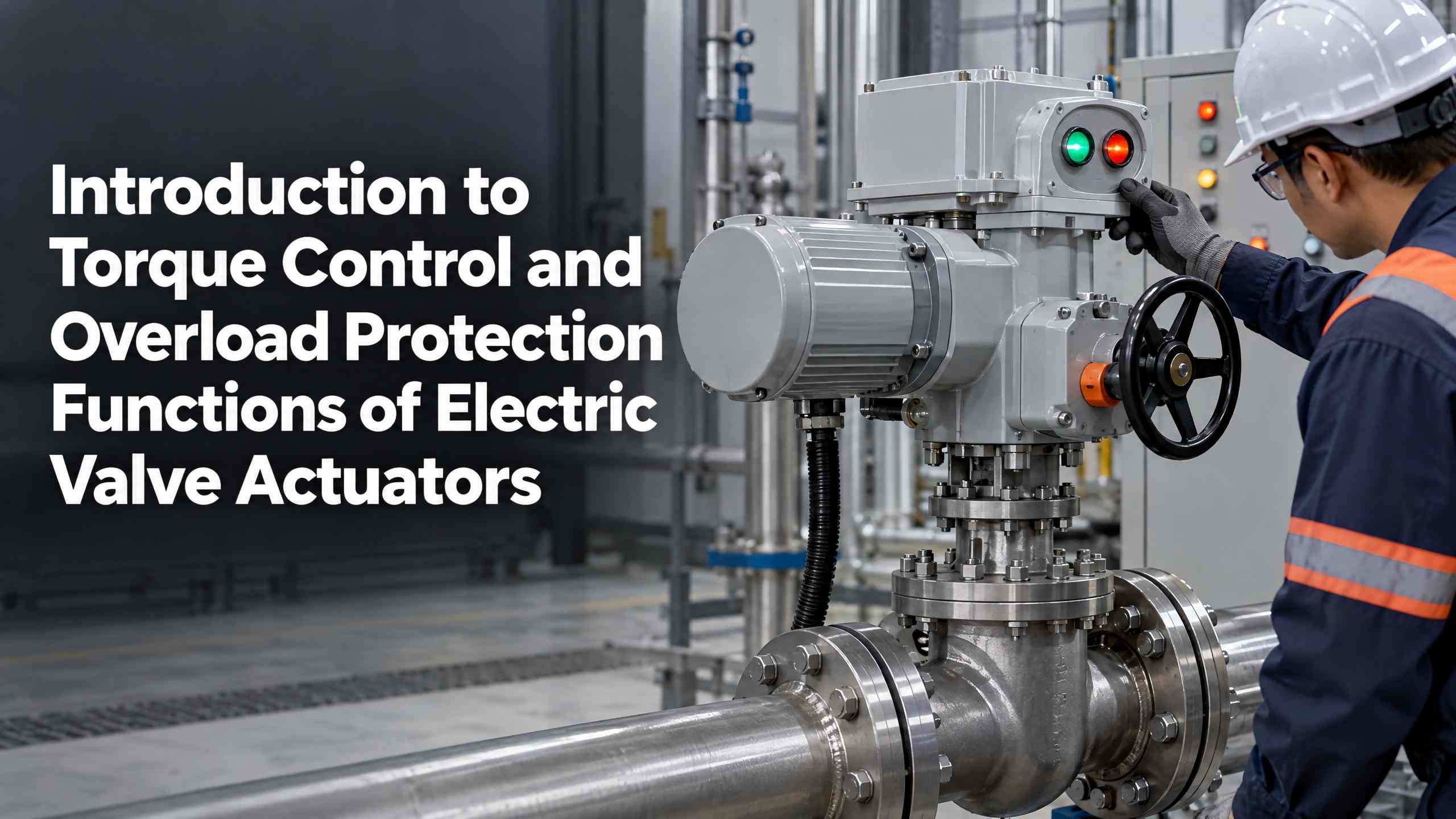
Valen Tech explains electric valve actuator torque control and overload protection functions. Learn how multi‑turn & part‑turn actuators prevent jamming and mechanical damage for petroleum, chemical, power and water pipeline systems.
Introduction to Torque Control and Overload Protection Functions of Electric Valve Actuators

This article compares on‑off and modulating electric actuators, covering their functional differences, control logic and application conditions to provide practical actuator selection guidance.
Detailed Explanation of the Differences Between On‑Off and Modulating Electric Actuators

This guide covers common electric‑actuator on‑site commissioning faults, causes & practical fixes. It delivers practical actuator commissioning troubleshooting for power, chemical and water‑treatment industry engineers.
Actuator Commissioning Troubleshooting: Causes and Complete Solutions