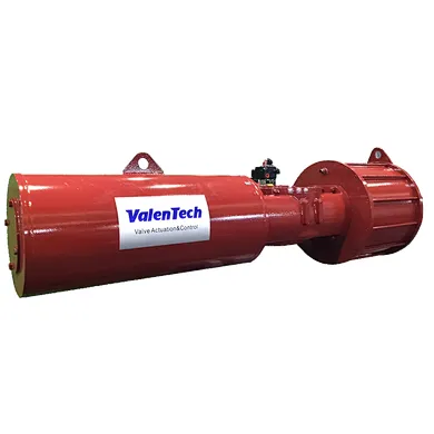
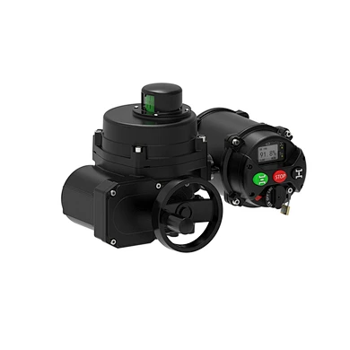
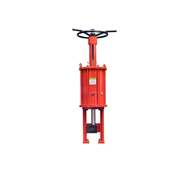
What Techniques Reducing Pneumatic Actuator Speed
How Air Flow Rate Directly Impacts Speed
Let's zoom in on this critical relationship. Think of filling a balloon: the pressure inside builds up, but how fast it inflates depends on how quickly you can push air into it (the flow rate). Similarly, for a pneumatic cylinder, pressure provides the force, but the flow rate dictates how quickly the volume of the cylinder can be filled or emptied, and therefore how fast the piston can move.
The volumetric flow rate required by an actuator is the product of the piston's area and its velocity.
Required Flow Rate = Piston Area × Velocity
This simple relationship shows that for a given cylinder size (fixed piston area), achieving a higher velocity directly requires a proportionally higher volumetric flow rate of air.
Conversely, if the air supply system (compressor capacity, piping, valves, tubing, fittings, flow control valves) can only deliver or exhaust air at a limited flow rate, that limited flow rate will constrain the piston's velocity, regardless of how high the pressure is.
Analogy: Imagine pushing a car. Pressure is like how hard you can push (potential force). Flow rate is like how much air you have in your lungs to sustain the push (power delivery). A strong person with limited breath can push hard initially but can't sustain a fast push over distance. A person with high endurance (high "flow rate") can push faster for longer. In pneumatics, undersized components anywhere in the path from the compressor to the actuator can act like a pinched hose, severely limiting the flow rate and crippling potential speed.
Therefore, optimizing air flow rate throughout the entire pneumatic circuit is absolutely essential for achieving high-speed pneumatic actuator performance.
What Techniques Reducing Pneumatic Actuator Speed
While achieving maximum speed is a common goal, engineers often need to reduce or precisely control pneumatic actuator speed below its maximum capability. This is done for various reasons, such as ensuring smooth motion, preventing damage from hard stops, synchronizing movements, or handling delicate products. Here's what you'd do:
Utilize Flow Control Valves (Restrictors): This is the most prevalent method. These valves are installed in the air lines to intentionally create a restriction, limiting the rate at which air can flow into or out of the cylinder.
Metering Out: Restricting the air exhausting from the cylinder is the most common technique. This creates back pressure on the side of the piston where air is being expelled, providing a controlled resistance that slows the movement. Metering out generally provides smoother speed control than metering in because the air on the driving side remains at full pressure, providing a stiffer, less spongy movement against the regulated exhaust.
Metering In: Restricting the air entering the cylinder. This limits the rate at which pressure can build up on the driving side. While it also reduces speed, the air on the exhaust side is unrestricted, which can lead to less stable or "spongy" motion, especially under varying loads. Metering in is less common for general speed control but might be used in specific applications.
Reduce Supply Pressure: Lowering the pressure via a regulator reduces the force available to move the piston (F=P*A). With less force, the acceleration is lower, and the achievable speed against the load and friction is reduced. However, this method also reduces the actuator's force capability, which might be unacceptable if the actuator needs to perform work (like clamping or lifting) that requires a minimum force.
Add Cushioning or Shock Absorbers: While primarily used to decelerate the piston smoothly at the end of its stroke to prevent impact damage, adjustable cushioning built into the actuator end caps or external hydraulic shock absorbers also affect the overall speed profile, particularly near the stroke ends. They absorb the kinetic energy of the moving mass. While not a primary method for controlling speed mid-stroke, they are essential for managing speed at the end of travel in high-speed applications.
Use Smaller Diameter Tubing or Fittings: While generally avoided for speed maximization, intentionally using longer runs of smaller diameter tubing or more restrictive fittings can limit the flow rate and thus reduce speed. This is less precise than using flow control valves but can have an effect.
Select Valves with Lower Flow Ratings: Using a valve with a flow capacity lower than the actuator and tubing's maximum capability will bottleneck the system and reduce speed. This is often a consequence of improper component sizing rather than an intentional control strategy, but it illustrates the principle.
The choice of method depends on the specific requirements: for smooth, adjustable speed reduction without sacrificing force, flow control valves (metering out) are typically the preferred solution.
The High-Speed Pneumatic Actuator
While any pneumatic actuator can move quickly if given enough air flow and a light load, a true "high-speed pneumatic actuator" is often designed with specific features to excel at rapid, repetitive cycling:
Optimized Internal Passages and Ports: Designed for maximum airflow, often with larger port sizes than standard cylinders of the same bore.
Low Friction Seals: Specialized seal materials and designs minimize breakaway and running friction, allowing force to translate more effectively into acceleration.
Lightweight Piston Assembly: Reducing the mass of the moving components boosts acceleration potential.
Robust Cushioning: Effective internal air cushioning or the expectation of external shock absorbers is built into the design to reliably manage the high kinetic energy at the end of rapid strokes, preventing damage over millions of cycles.
Durable Construction: Components are selected to withstand the increased stresses and temperatures generated by high-speed, high-cycle operation.
These actuators are not just standard cylinders pushed to their limits; they are engineered specifically for demanding applications where speed and cycle rate are paramount, such as sorting, rapid clamping, or indexing mechanisms. They often work in conjunction with high-flow, fast-switching valves and a well-designed air supply system to unleash their full speed potential.
Balancing Speed and Control for Your Application
While the allure of high-speed automation is clear (faster processes!), pursuing speed without considering its implications can lead to significant challenges and unexpected costs.
Energy Consumption and Cost: Moving air quickly consumes significantly more energy. The inherent inefficiency of compressed air generation is magnified at high flow rates. High-speed pneumatic systems can be major energy hogs if not designed carefully.
Wear and Lifespan: Higher speeds and accelerations mean more dynamic stress on seals, bearings, and cushioning. Increased friction can generate heat. Actuators in high-speed applications experience accelerated wear and may require more frequent maintenance or have a shorter lifespan compared to those operating at moderate speeds.
Heat Generation: While pneumatics don't have the electrical heat issues of motors, the compression of air and the dissipation of energy during cushioning create heat. In high-cycle applications, this can be a factor.
Noise: Rapid air exhaust from fast-cycling valves can be noisy. Mufflers can reduce noise but may slightly impact speed due to flow restriction.
Safety: As discussed earlier, moving mass at high speed creates significant kinetic energy. This necessitates robust safety guarding, reliable emergency stop procedures, and careful consideration of potential failure modes. Controlling these energetic movements reliably requires effective braking or cushioning mechanisms.
Control Complexity (Relative): While simpler than servo electrics for complex profiles, achieving repeatable speed control with pneumatics, especially under varying loads or pressures, requires careful selection and tuning of flow control valves.
Choosing Your Partner for Speed
Navigating the requirements for high-speed pneumatic actuation involves more than just picking a cylinder with a high velocity rating. It requires a holistic understanding of how the actuator, the directional control valve, flow control valves, air preparation units, tubing, fittings, and the overall air supply system interact.
As a valve actuator manufacturer, we understand these dynamics intimately. We design and produce valves with optimized flow characteristics and offer insights into selecting the right actuator bore size, stroke, and cushioning for your speed and load requirements. We can guide you in choosing the appropriate flow control methods and ensuring that your valve is not the bottleneck limiting your actuator's potential speed.
Partnering with a knowledgeable supplier ensures that you select components that are not only individually high-performing but also work together seamlessly to deliver the controlled, high-speed motion your application demands, balancing performance targets with considerations for efficiency, durability, and safety.
Mastering Pneumatic Speed for Peak Performance
Pneumatic actuators offer a compelling solution for applications requiring rapid, simple motion. Achieving true "high speed" with these devices depends on a delicate balance between generating sufficient force (pressure and piston area) and, more critically, ensuring a free and ample flow of air throughout the system – from the compressor, through the pipes and valves, into and out of the cylinder ports.
While inherent actuator design features and air supply capabilities set the speed potential, control components like flow control valves are essential for regulating and optimizing speed below maximum levels. However, pursuing speed comes with trade-offs in terms of energy consumption, wear, safety, and noise that must be carefully evaluated.