How to Select Part‑Turn, Linear‑Stroke and Multi‑Turn Electric Actuators
author: ATHENA GROUP
2026-10-22
Electric actuators serve as the core drive for automated valves, responsible for valve opening/closing and flow regulation in water treatment, HVAC, chemical, power, energy pipeline and other systems. As a professional actuator brand, Valen Tech frequently receives inquiries from procurement and automation control engineers: how do you choose between part‑turn, linear‑stroke and multi‑turn electric actuators?
In fact, the selection logic is not complicated — the core is to match the valve’s motion pattern. By identifying how the valve moves and combining it with working condition parameters, you can quickly lock in the suitable model. Below is a breakdown of the characteristics of the three types of actuators, a side‑by‑side comparison, and a complete set of selection procedures.
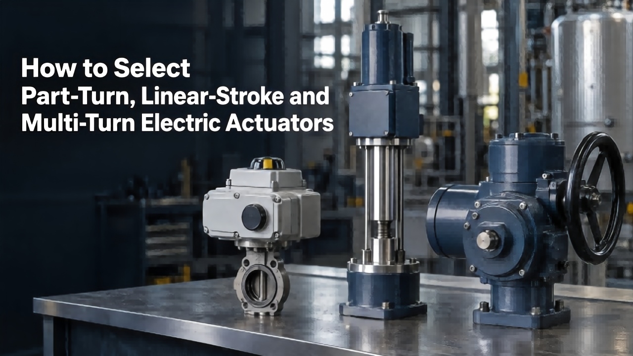
I. Part‑Turn Electric Actuators: Suitable for Angle‑Type Opening‑Closing Equipment
The core feature of part‑turn electric actuators is rotation within a limited angle; the normal operating rotation angle is mainly 90°, and certain special models can meet 180° rotation requirements. Its output form is mainly driven by torque. Featuring a compact structure and small footprint, the equipment delivers simple opening‑closing procedures and stable operation. It is suitable for fluid‑control equipment that only requires small‑angle rotation to achieve full‑open, full‑closed and fine‑tuning functions.
In industrial scenarios, such actuators are mainly paired with ball valves, butterfly valves and plug valves — their opening‑closing logic is highly consistent with angular motion, enabling medium on‑off and flow regulation without complex transmission structures. They are also widely adopted for regulating dampers of various industrial air ducts and flue gas ducts, accurately matching air duct opening‑degree adjustment for conventional working conditions such as ventilation, heat exchange and flue‑gas treatment.
In terms of operating performance, part‑turn electric actuators deliver smooth response and adapt to scenarios with frequent start‑stop and small‑range regulation. They support flexible installation via direct connection, base crank and other forms, making them common equipment in light industry, water treatment and HVAC fields.
II. Linear‑Stroke Electric Actuators: Suitable for Linear Lifting‑Type Regulation Equipment
Linear‑stroke electric actuators perform vertical reciprocating linear motion. Their core output power is thrust, which can directly drive valve stems to complete lifting movements for valve opening/closing and precise regulation of medium flow and pressure. Unlike rotary actuators, they have no rotary transmission structure. Power acts directly on valve stems, resulting in lower transmission loss and higher regulation accuracy.
Such actuators are exclusively designed for valves whose stems perform linear lifting movements, mainly control valves and globe valves. These valves adjust flow‑channel cross‑sectional area via stem lifting to achieve precise regulation, which perfectly matches the motion logic of linear‑stroke actuators and meets the demands of high‑precision working conditions. In industrial scenarios including fine chemical regulation, power pipe network control and precise flow cut‑off for water treatment, they are used for refined regulation of pipeline medium pressure and flow.
Linear‑stroke electric actuators offer a wide range of thrust output specifications to fit equipment of different calibers and pressure grades. They deliver accurate displacement control and are suitable for automatic control systems with high requirements for regulation precision and operational stability.
III. Multi‑Turn Electric Actuators: Suitable for Heavy‑Duty Equipment Requiring Multi‑Rotation Opening‑Closing
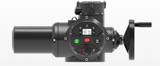
The output shaft of multi‑turn electric actuators can perform continuous multi‑cycle forward and reverse rotation with no fixed rotation‑angle limit. It drives valve‑stem lifting to open and close valves through multi‑cycle rotation. Boasting sufficient power reserve, high load‑bearing capacity and a stable transmission structure, the equipment adapts to high‑load and high‑resistance working conditions. Its body is suitable for heavy‑duty industrial equipment.
In industrial applications, such actuators are mainly paired with gate valves and large‑size globe valves that require multiple rotations to complete full opening and full closing. These valves feature long opening‑closing strokes and cannot realize on‑off functions with a single rotation, which calls for the continuous rotary power of multi‑turn actuators. Most heavy‑duty pipeline valves of large caliber and high pressure are also driven by multi‑turn actuators.
Multi‑turn electric actuators feature durable structures and strong resistance to load impact, and can run under high loads for long periods. They are commonly used in energy pipelines, large‑scale water conservancy projects, heavy‑industry fluid‑control systems and other fields. Their controllable opening‑closing speed effectively guarantees safe operation of heavy‑duty fluid equipment.
IV. Comparison Table of Three Types of Electric Actuators
| Type | Motion Mode | Core Output | Matching Valves | Typical Working Conditions |
|---|---|---|---|---|
| Part‑Turn | 90° (up to 180°) rotation | Torque | Ball valves, butterfly valves, plug valves, dampers | Frequent start‑stop, small‑range regulation; light industry / water treatment / HVAC |
| Linear‑Stroke | Vertical reciprocating linear motion | Thrust | Control valves, globe valves | Precise throttling; chemical / power / water treatment fine‑tuning |
| Multi‑Turn | Continuous multi‑cycle forward‑reverse rotation | High torque | Gate valves, large‑size globe valves | High‑pressure & large‑caliber; energy / water conservancy / heavy industry |
Selection Mnemonic: Select the actuator whose motion pattern matches that of the valve.
V. Complete 5‑Step Selection Procedure for Electric Actuators
1. Confirm valve type (top priority)
90° rotary opening‑closing (butterfly valves, ball valves) → Part‑Turn; linear lifting valve stem (control valves) → Linear‑Stroke; multi‑cycle rotary switching (gate valves) → Multi‑Turn. Mismatched motion patterns represent the most common and costliest selection error.
2. Calculate torque / thrust and set aside safety margin
For part‑turn and multi‑turn actuators, focus on torque; for linear‑stroke actuators, focus on thrust. The rated output of the actuator must exceed the actual demand of the valve. A safety margin of 25%‑30% is recommended. Take extreme working conditions such as medium pressure, internal valve friction and scaling/jamming into account during calculation.
3. Verify power supply and control signals
Confirm operating mode: On‑Off type / Modulating type (4‑20 mA, 0‑10 V analog signal); power supply: 220 VAC, 380 VAC, 24 VDC, etc. Incompatible power supply and signals will prevent the whole system from connecting to automatic controls.
4. Determine operating speed and duty cycle
Quick opening‑closing is required for emergency shut‑off; high‑duty‑cycle actuators are needed for continuous modulation. Ordinary on‑off actuators will overheat and burn out under frequent continuous operation.
5. Evaluate service environment and installation standards
Use explosion‑proof models for hazardous explosive areas; select units with IP67 or higher protection rating and anti‑corrosion housings for outdoor exposed installation. Flange standards: ISO 5211 for part‑turn actuators and ISO 5210 for multi‑turn actuators to guarantee docking compatibility with valves.
VI. Common Pitfalls in Actuator Selection
1. Prioritizing price comparison while ignoring working‑condition parameters — low‑cost actuators are highly prone to damage under high‑temperature and high‑pressure conditions.
2. Failure to reserve safety margin — when the rated torque just meets the demand, valves will jam in case of medium fluctuation or scaling.
3. Confusing motion types: driving gate valves with part‑turn actuators — hardware structure mismatch will damage valve stems or gears under forced operation.
4. Overlooking control signals: equipping analog modulation loops with ordinary two‑position on‑off actuators, which disables automatic regulation.
5. Neglecting environmental protection ratings: deploying indoor‑type actuators outdoors or in explosive‑proof zones, which creates potential safety hazards.
VII. FAQ
Q1: What are the differences between part‑turn and multi‑turn electric actuators?
A: Part‑turn actuators only rotate 90° (up to 180°) to complete switching and fit butterfly valves and ball valves. Multi‑turn actuators require continuous multi‑cycle rotation for gate valves and large‑size valves, delivering longer strokes and higher torque.
A: Part‑turn actuators only rotate 90° (up to 180°) to complete switching and fit butterfly valves and ball valves. Multi‑turn actuators require continuous multi‑cycle rotation for gate valves and large‑size valves, delivering longer strokes and higher torque.
Q2: Can linear‑stroke actuators drive ball valves?
A: No direct matching is available. Ball valves require rotary motion, while linear‑stroke actuators deliver linear push‑pull movement. Their motion patterns are incompatible.
A: No direct matching is available. Ball valves require rotary motion, while linear‑stroke actuators deliver linear push‑pull movement. Their motion patterns are incompatible.
Q3: Which type of electric actuator is the most widely used?
A: Part‑turn electric actuators. Ball valves and butterfly valves have the largest consumption in pipeline systems, and accordingly part‑turn actuators enjoy the broadest market application.
A: Part‑turn electric actuators. Ball valves and butterfly valves have the largest consumption in pipeline systems, and accordingly part‑turn actuators enjoy the broadest market application.
Q4: How is torque calculated?
A: The rated torque of the actuator should be 25%‑30% higher than the maximum torque required by the valve under working conditions. Harsh conditions including pressure, friction and impurities shall all be incorporated into calculation.
A: The rated torque of the actuator should be 25%‑30% higher than the maximum torque required by the valve under working conditions. Harsh conditions including pressure, friction and impurities shall all be incorporated into calculation.
VIII. Summary
The core principle for selecting part‑turn, linear‑stroke and multi‑turn electric actuators is to match the valve’s motion pattern.
90° rotary opening‑closing valves → Part‑Turn; valves with linearly‑lifting stems → Linear‑Stroke; valves requiring multi‑cycle rotation for switching → Multi‑Turn.
90° rotary opening‑closing valves → Part‑Turn; valves with linearly‑lifting stems → Linear‑Stroke; valves requiring multi‑cycle rotation for switching → Multi‑Turn.
Need one‑on‑one selection support? Please visit Valen Tech official website 【www.valen‑tech.com】to browse the full series of electric actuators, or send project documents to【 k.pan@athenavalve.com 】for technical selection and solution assessme
Response Speed of Switch‑Type Electric Actuator
Related Article
Learn about electric actuator response speed, internal and external influencing factors and key selection points, to select suitable actuators for valve automation projects and ensure efficient and stable system operation.
Response Speed of Switch‑Type Electric Actuator
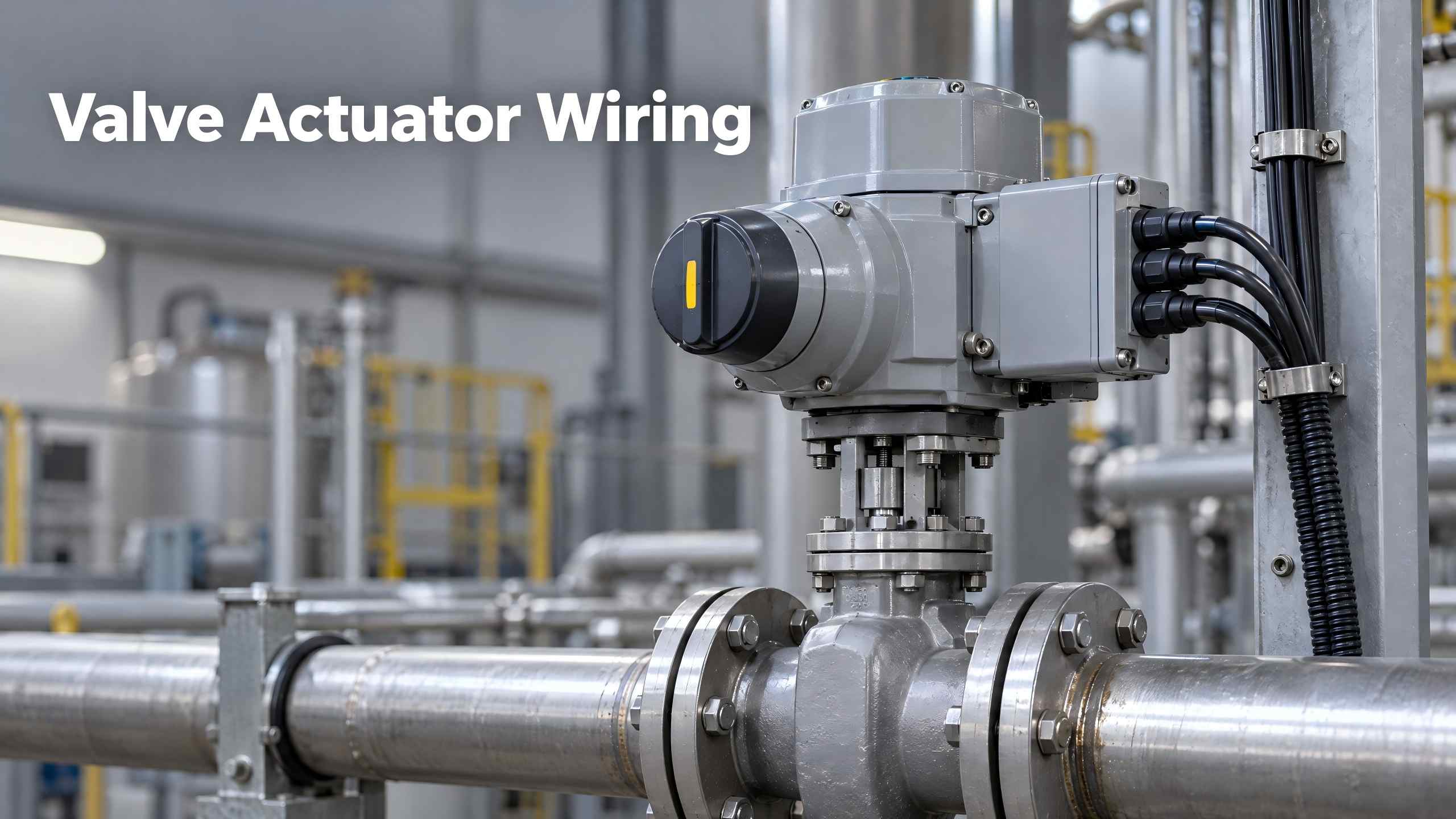
Valve Actuator Wiring describes wiring, commissioning and troubleshooting for electric valve actuators, guiding technicians to adopt standard wiring for stable industrial control.
Valve Actuator Wiring
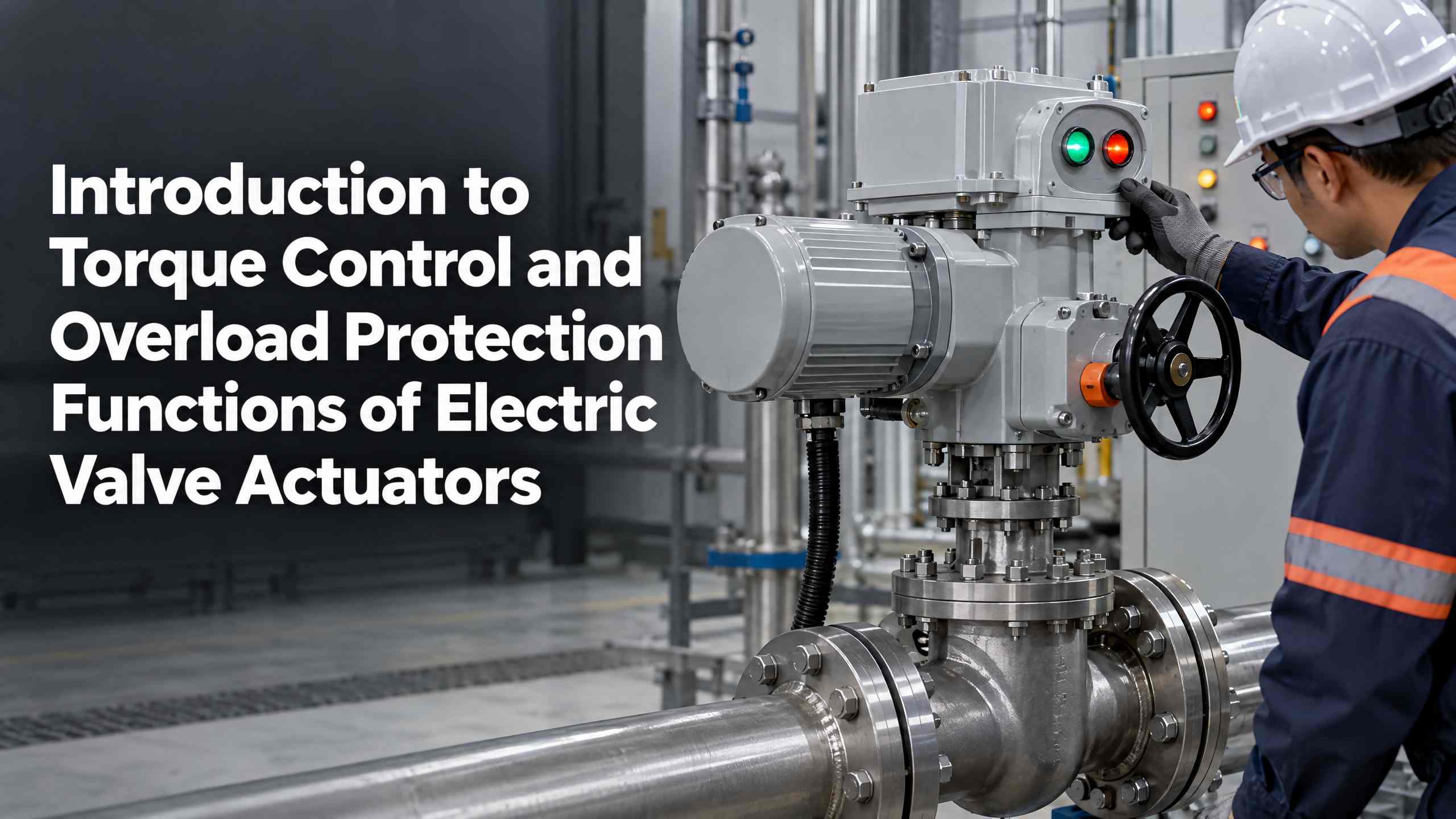
Valen Tech explains electric valve actuator torque control and overload protection functions. Learn how multi‑turn & part‑turn actuators prevent jamming and mechanical damage for petroleum, chemical, power and water pipeline systems.
Introduction to Torque Control and Overload Protection Functions of Electric Valve Actuators