
Pneumatic Valve Positioner Troubleshooting: Common Malfunctions, Diagnostic Procedures and Solutions
author: ATHENA GROUP
2026-06-24
Pneumatic valve positioners are core control components in automation systems of chemical industry, power generation, water treatment and oil & gas sectors. They receive 4–20mA signals to accurately adjust valve opening degrees. During long-term operation, issues such as contaminated air supply, pressure fluctuations, calibration drift, circuit abnormalities and mechanical wear often lead to malfunctions including valve inaction, position deviation, jitter and slow response, which undermine production stability. Combining practical field maintenance experience, this document standardizes troubleshooting procedures and solutions for frequent faults to facilitate rapid fault localization and repair.
I. Pre-Fault Preliminary Inspection
Most positioner malfunctions stem from abnormal air supply, control signals or operating environments rather than hardware damage. Three basic preliminary inspections must be completed prior to maintenance.
1.Air Supply System Inspection
Standard operating pressure ranges from 0.4 to 0.6 MPa (4–7 bar / 60–100 psi). Insufficient pressure results in insufficient driving force, while excessive pressure accelerates component aging. Inspect pressure reducing valves, air pipeline leakage and water/dust accumulation in filters. Moisture and impurities are major causes of valve sticking and slow response. Install a pressure stabilizer if severe pressure fluctuations occur.
2.Control Signal and Circuit Inspection
Use a multimeter or loop calibrator to test the stability of 4–20mA signals, and check for loose, corroded or broken wiring. Electrical noise at site may cause signal disorder and unintended valve movement. HART tools can be used to read signal data for intelligent positioners.
3.Visual Appearance and Mechanical Inspection
Check for shell damage, air leakage and loose parts; observe whether valve stems are stuck and whether cams have loose fittings or abnormal noises. Mechanical deformation and loose fittings directly lead to inaccurate valve positioning.
II. Frequent Malfunction Phenomena, Root Causes and Quick Remedies
1.Valve Fails to Move at All
Common causes: cut-off air supply, broken signal wires, blocked air passages, stuck valve stems, damaged actuator diaphragms, mismatched actuator models.
Solutions: restore standard air supply pressure and clear impurities in air passages; repair faulty wiring; manually release stuck valve stems; replace damaged diaphragms and sealing parts; select properly sized actuators.
2.Valve Position Deviation and Inaccurate Opening
Mainly caused by zero/span drift, loose valve stems, fatigued springs and worn cams.
Core solutions: recalibrate zero and span; perform one-touch auto-tuning for intelligent positioners; fasten screws on valve stems and cams; replace fatigued springs to eliminate deviations from mechanical clearances.
3.Valve Jitter, Oscillation, Crawling and Hunting
Excessive positioner sensitivity, improper damping, air pressure fluctuations, minor air leakage and oversized actuators result in continuous small back-and-forth movement or stepwise crawling.
Remedies: adjust damping and sensitivity, stabilize air supply, repair air leakage, lubricate valve stems and replace actuators with matching specifications.
4.Slow Valve Movement and Delayed Response
Dirty air supply filter cartridges, blocked air passage orifices, water contained in air supply and scaling inside valve bodies create high resistance, which are primary inducing factors.
Solutions: clean air passages and exhaust channels of positioners, replace filter cartridges and remove impurities inside valve bodies to greatly improve response speed.
5.Sticking and Hysteresis
High startup resistance, jerky movement and inconsistent positioning between forward and reverse strokes. These problems are mainly triggered by insufficient lubrication and internal wear or minor leakage. They can be largely mitigated by lubricating transmission components, detecting and repairing air leakage, and performing recalibration.
6.Black Screen and Error Codes on Intelligent Positioners
Abnormal circuit power supply or main board failure. First inspect wiring and power supply; if no abnormality is found, repair or replace the main control board. Dedicated diagnostic software can quickly retrieve fault codes.
III. Standard Troubleshooting Procedures
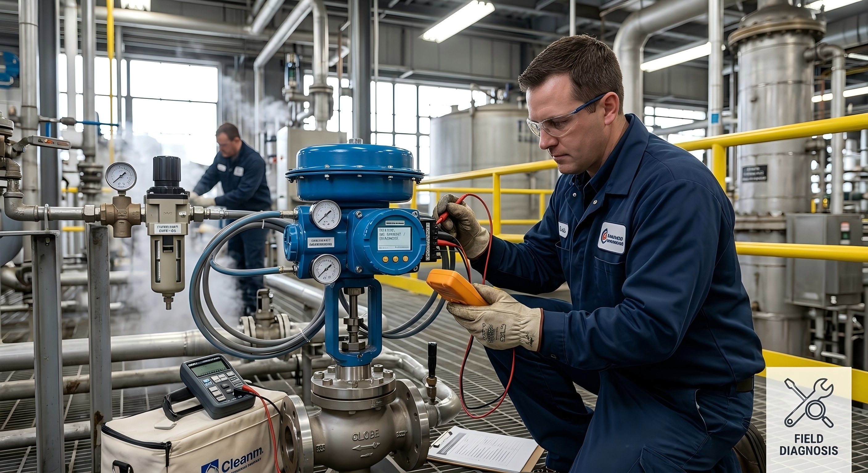
- Visual Inspection: Check for equipment damage, leakage, abnormal noises and irregular movement.
- Air Supply Test: Verify pressure parameters, clean filters and check for moisture and air leakage.
- Calibration Verification: Conduct full-stroke manual testing, calibrate zero and span, and use professional calibration tools to guarantee precision.
- Signal and Electrical Test: Measure input and output signals to eliminate circuit interference and poor contact issues.
IV. Routine Maintenance
- Perform positioner calibration regularly every 3 to 6 months.
- Conduct routine inspections of air pipelines, wiring, cams and fasteners.
- Replace air supply filter cartridges periodically to maintain clean air supply.
- Establish maintenance log records, standardize overhaul procedures and provide professional training for maintenance personnel to distinguish overhaul differences between conventional and intelligent positioners.
V. Frequently Asked Questions (FAQ)
Q1: How to address frequent calibration drift of positioners?
A: It is mostly caused by expired calibration, clogged air passages, loose mechanical fittings and fatigued springs. Regular calibration, clean air supply and fastened components can fundamentally resolve this issue.
Q2: The air supply pressure is normal, but the valve still jitters. How to fix it?
A: Adjust damping and sensitivity, inspect minor air leakage, reduce mechanical friction and verify the specification matching of the actuator.
Q3: What are the troubleshooting differences between conventional and intelligent positioners?
A: Conventional positioners rely on manual calibration and fault phenomenon analysis; intelligent positioners support auto-tuning, fault code diagnosis and bus data analysis for more efficient and accurate troubleshooting.
Conclusion
Efficient resolution of most on-site faults can be achieved by following the troubleshooting logic of "conduct preliminary inspections first, then target specific faults; check parameters first, then hardware" for pneumatic valve positioners. Maintaining clean air supply, accurate calibration, stable mechanical structures and intact circuits can effectively prevent common faults such as position deviation, sticking, oscillation and slow response, ensuring long-term stable operation of automated production systems.
What Are the Common Types of Valve Actuators
Is an Electric Gate Valve Your Best Choice?
Related Article
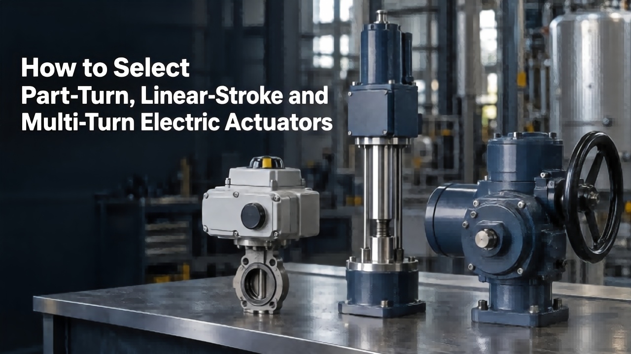
Learn differences among part‑turn, linear‑stroke and multi‑turn electric actuators. This guide covers matching valves, torque‑thrust calculation, 5‑step selection process and typical pitfalls for your industrial actuator applications.
How to Select Part‑Turn, Linear‑Stroke and Multi‑Turn Electric Actuators

Learn about electric actuator response speed, internal and external influencing factors and key selection points, to select suitable actuators for valve automation projects and ensure efficient and stable system operation.
Response Speed of Switch‑Type Electric Actuator
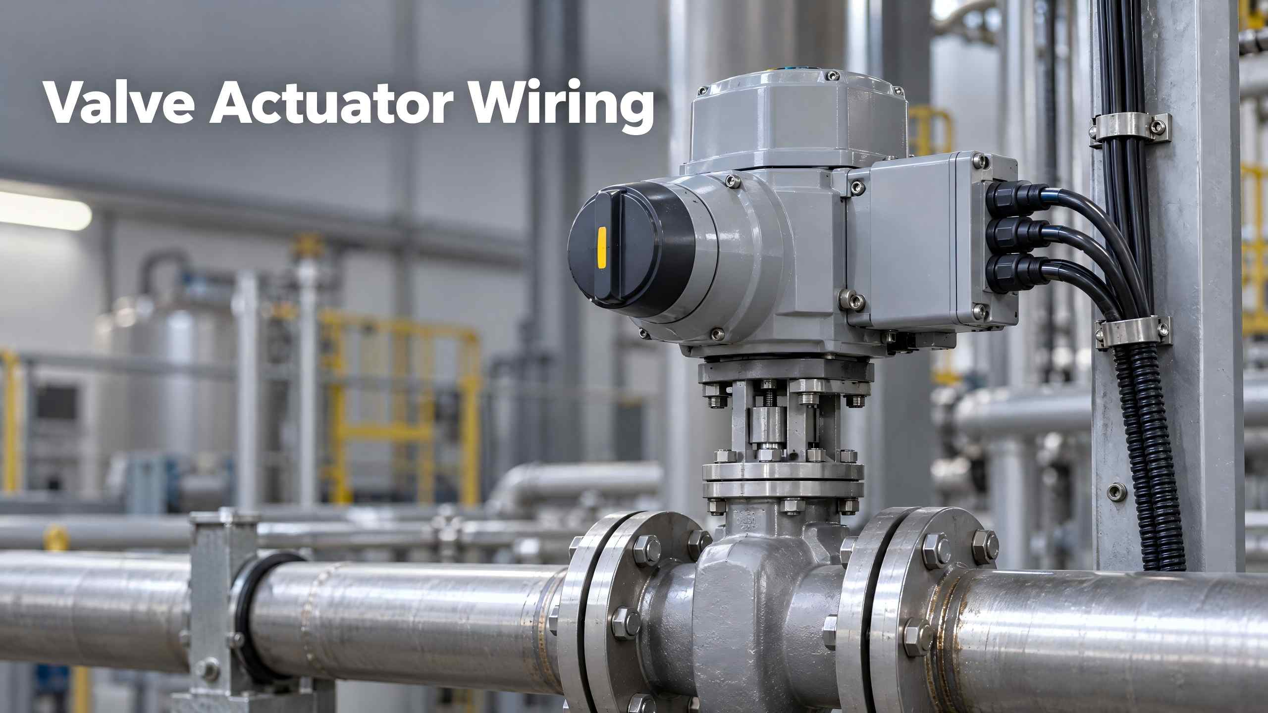
Valve Actuator Wiring describes wiring, commissioning and troubleshooting for electric valve actuators, guiding technicians to adopt standard wiring for stable industrial control.
Valve Actuator Wiring
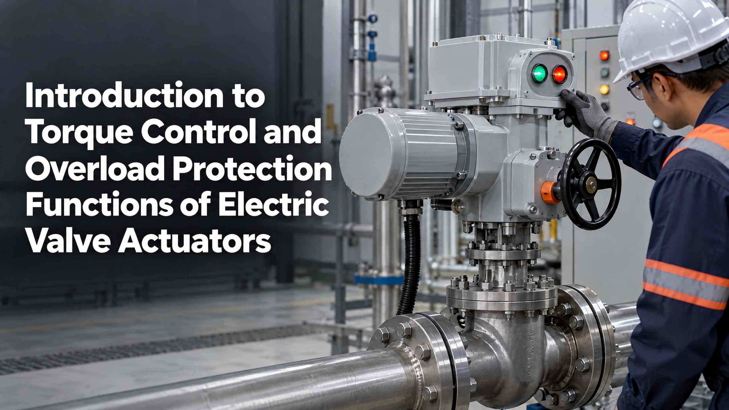
Valen Tech explains electric valve actuator torque control and overload protection functions. Learn how multi‑turn & part‑turn actuators prevent jamming and mechanical damage for petroleum, chemical, power and water pipeline systems.
Introduction to Torque Control and Overload Protection Functions of Electric Valve Actuators