
Guide for Matching Valves with Electric Actuators
author: ATHENA GROUP
2025-10-15
The connection methods between electric actuators and valves mainly include flange connection, threaded connection, wafer connection, clamp connection, welding connection, etc. Each of these connection methods has its own characteristics and is suitable for different application scenarios. According to surveys, 28% of problems are caused by wrong selection of connection methods and improper installation. Therefore, mastering the common connection methods between actuators and valves and the key points of matching logic is a core skill for engineers and purchasers. When selecting a suitable connection method, you can refer to Valentech's electric actuator products, which are compatible with various valve connection methods, operate stably, and are widely used in the field of industrial automation control. This article will analyze the characteristics, application scenarios, and selection skills of 4 types of mainstream connection methods to help you avoid most wrong matching problems.
1. Five Mainstream Connection Methods Between Electric Actuators and Valves
01 Flange Connection
This is the most commonly used connection form in valves. Based on the ISO 5211 international standard, the actuator flange and the valve flange are rigidly fixed by bolts to achieve stable torque transmission. Flange connections can be divided into multiple types according to the shape of the joint surface, such as smooth type, concave-convex type, tongue-and-groove type, trapezoidal groove type, lens type, and O-ring type, which are suitable for valves under different pressure and temperature conditions. Flange connection has the advantages of convenient installation and disassembly and reliable sealing, and is more common in high-pressure and large-diameter valves.
- Applicable Scenarios
Valve Types: Most industrial valves such as butterfly valves, ball valves, gate valves, globe valves, especially suitable for large-diameter valves above DN80.
Working Conditions: Scenarios with high pressure and high torque requirements.
Industry Fields: Petrochemical, municipal pipe network, power energy, water treatment and other scenarios with high requirements for connection stability.
Working Conditions: Scenarios with high pressure and high torque requirements.
Industry Fields: Petrochemical, municipal pipe network, power energy, water treatment and other scenarios with high requirements for connection stability.
- Key Selection Points
Confirm Flange Specifications: Match the corresponding ISO 5211 specifications according to the nominal diameter and torque requirements of the valve.
Check Bolt Compatibility: The number and diameter of bolt holes of the actuator and valve flanges must be exactly the same to avoid flange deformation caused by forced installation.
Select Sealing Accessories: Oil-resistant / temperature-resistant gaskets should be installed on the flange contact surface to prevent medium leakage or external dust from entering.
Check Bolt Compatibility: The number and diameter of bolt holes of the actuator and valve flanges must be exactly the same to avoid flange deformation caused by forced installation.
Select Sealing Accessories: Oil-resistant / temperature-resistant gaskets should be installed on the flange contact surface to prevent medium leakage or external dust from entering.
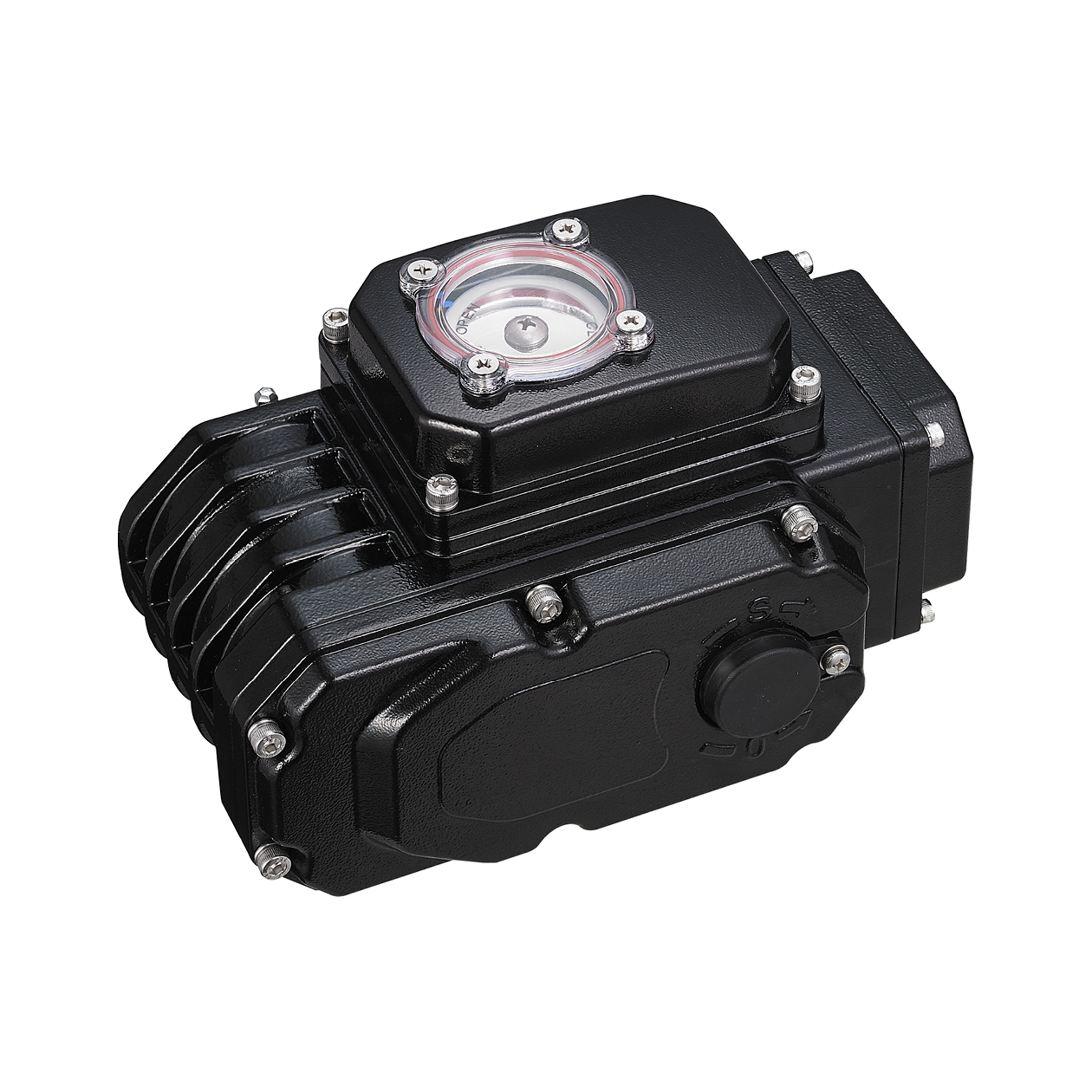
02 Wafer Connection
Wafer connection is a connection form that directly fixes the valve, electric actuator and pipelines at both ends by bolts, so that the entire system can be tightly combined to achieve effective control and operation. The wafer connection method has the characteristics of simple structure and convenient installation, and is suitable for various specifications of valves and actuators, and can meet most application occasions.
- Applicable Scenarios
Space-constrained Fields: Such as central air-conditioning terminals (fan coil valve connection), ship pipelines (narrow space in the cabin), pharmaceutical equipment (compact layout in clean rooms).
Small and medium-diameter, medium and low-pressure working conditions: Medium pressure ≤ PN16 (about 1.6MPa), diameter DN25 - DN300 pipelines for water, air, light oil and other media.
Scenarios with quick disassembly and assembly requirements: Such as food and beverage production lines (regular cleaning and replacement of valves), laboratory temporary pipeline systems.
Small and medium-diameter, medium and low-pressure working conditions: Medium pressure ≤ PN16 (about 1.6MPa), diameter DN25 - DN300 pipelines for water, air, light oil and other media.
Scenarios with quick disassembly and assembly requirements: Such as food and beverage production lines (regular cleaning and replacement of valves), laboratory temporary pipeline systems.
- Key Selection Points
Confirm Valve Wafer Standard: Ensure that the actuator installation interface is compatible with the valve wafer structure.
Match Bolt Specifications and Materials: Select the number of bolts according to the valve diameter and pressure, and 304 stainless steel is preferred for the material.
Limit Working Condition Boundaries: Strictly control the medium pressure ≤ PN16 and temperature -20℃ ~ 120℃.
Match Bolt Specifications and Materials: Select the number of bolts according to the valve diameter and pressure, and 304 stainless steel is preferred for the material.
Limit Working Condition Boundaries: Strictly control the medium pressure ≤ PN16 and temperature -20℃ ~ 120℃.
03 Welding Connection
The welding connection between the electric actuator and the electric valve is a method of tightly connecting the two by welding. This connection method is usually suitable for equipment that needs to be used stably for a long time, such as chemical, papermaking, power and other equipment fields. Welding connection has the advantages of good connection tightness, high reliability and relatively long service life, and generally no water leakage occurs. It is only suitable for scenarios without maintenance requirements or extremely harsh working conditions.
- Applicable Scenarios
Valve Types: Globe valves and gate valves under special working conditions, such as subsea pipeline valves, high-temperature and high-pressure power station valves.
Working Conditions: Extremely harsh environments (such as deep sea, desert, highly corrosive chemical workshops), scenarios with no maintenance space or extremely high maintenance costs.
Industry Fields: Marine engineering (subsea oil pipelines), nuclear industry (valves in radioactive environments), high-temperature power stations (boiler high-temperature valves).
Working Conditions: Extremely harsh environments (such as deep sea, desert, highly corrosive chemical workshops), scenarios with no maintenance space or extremely high maintenance costs.
Industry Fields: Marine engineering (subsea oil pipelines), nuclear industry (valves in radioactive environments), high-temperature power stations (boiler high-temperature valves).
- Key Selection Points
Confirm Material Compatibility: The material of the actuator base (such as carbon steel, 316L stainless steel) must be consistent with the material of the valve body to avoid cracks caused by dissimilar steel welding.
Select Welding Process: Argon arc welding is preferred for high-temperature working conditions, and anti-corrosion treatment after welding is required in corrosive environments.
Evaluate Maintenance Costs: Confirm in advance whether maintenance is required during the life cycle of the equipment. If frequent maintenance is required, welding connection is strictly prohibited.
Select Welding Process: Argon arc welding is preferred for high-temperature working conditions, and anti-corrosion treatment after welding is required in corrosive environments.
Evaluate Maintenance Costs: Confirm in advance whether maintenance is required during the life cycle of the equipment. If frequent maintenance is required, welding connection is strictly prohibited.
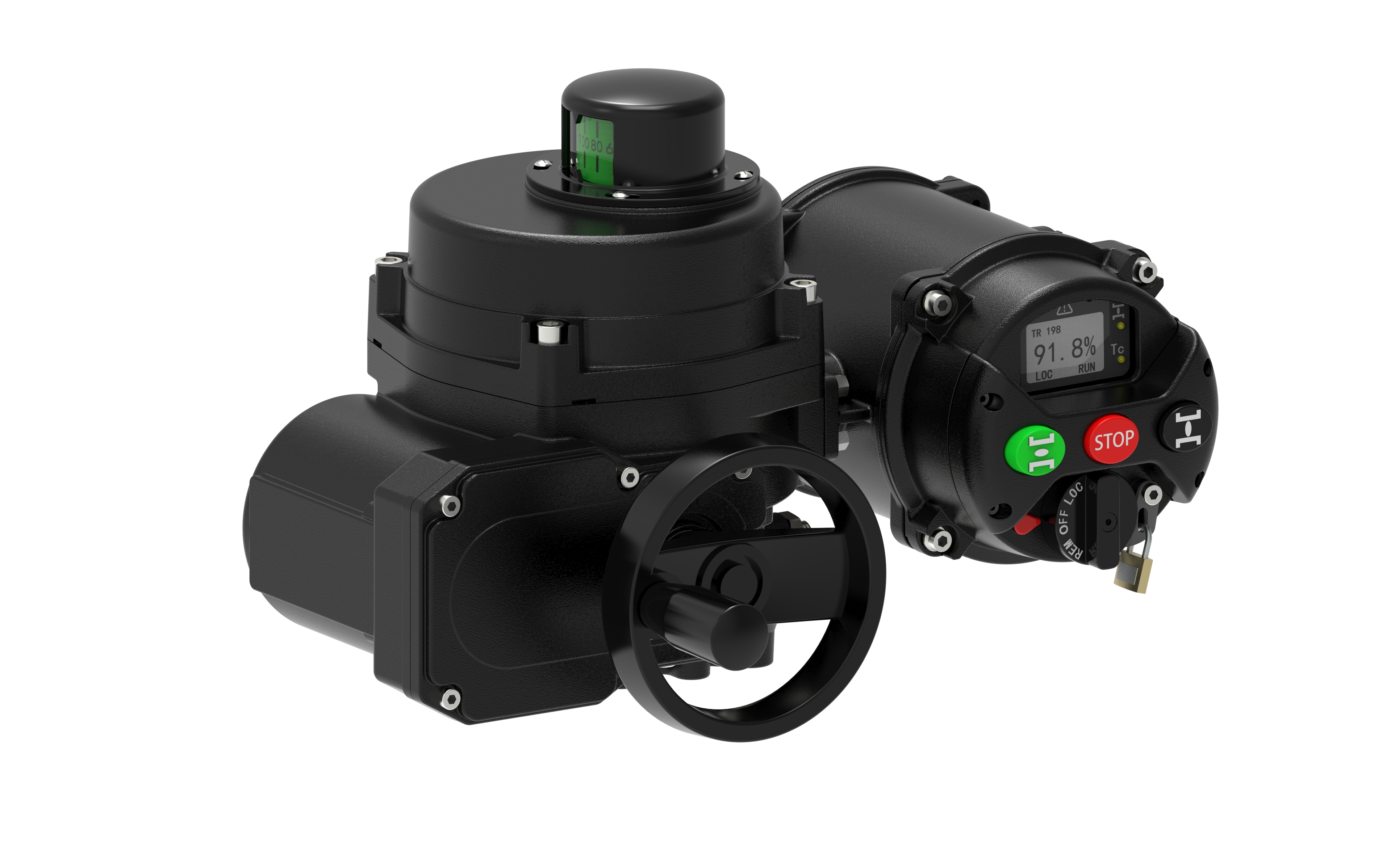
04 Threaded Connection
Threaded connection is a way to realize the connection between the actuator and the valve through the screwing action of internal and external threads. According to the sealing principle, it can be divided into direct sealing and indirect sealing. With the characteristics of simple structure, light weight and convenient disassembly and assembly, it has become a typical solution for matching small valves and actuators, and is commonly used in small valves and actuators, including butterfly valves, ball valves, plug valves, etc.
- Direct Sealing: The thread itself realizes sealing
Principle: When the internal and external threads are tightened, the close fit between the thread profiles directly blocks the medium leakage channel.
Characteristics: No additional sealing elements are required, the structure is extremely simple, but the thread processing accuracy is very high, and long-term vibration is easy to cause thread loosening, and the risk of seal failure increases with time.
Applicable Scenarios: Low-pressure (≤1.6MPa), small-diameter (DN6 - DN25) scenarios where the medium is not highly corrosive, such as small laboratory pipelines, connection between household gas valves and actuators.
Characteristics: No additional sealing elements are required, the structure is extremely simple, but the thread processing accuracy is very high, and long-term vibration is easy to cause thread loosening, and the risk of seal failure increases with time.
Applicable Scenarios: Low-pressure (≤1.6MPa), small-diameter (DN6 - DN25) scenarios where the medium is not highly corrosive, such as small laboratory pipelines, connection between household gas valves and actuators.
- Indirect Sealing: Rely on gaskets to enhance sealing
Principle: The thread only provides "fastening force" to compress the connection end faces of the actuator and the valve, and realizes medium sealing through the sealing gasket between the two planes.
Characteristics: The sealing reliability is much higher than that of direct sealing. The gasket can be flexibly selected according to the characteristics of the medium, and when the thread is loose, the gasket can still maintain the seal for a short time.
Applicable Scenarios: Medium and low-pressure (≤4MPa), small and medium-diameter (DN6 - DN50) industrial scenarios, such as small chemical instrument valves, connection between sampling valves of pharmaceutical equipment and actuators.
Characteristics: The sealing reliability is much higher than that of direct sealing. The gasket can be flexibly selected according to the characteristics of the medium, and when the thread is loose, the gasket can still maintain the seal for a short time.
Applicable Scenarios: Medium and low-pressure (≤4MPa), small and medium-diameter (DN6 - DN50) industrial scenarios, such as small chemical instrument valves, connection between sampling valves of pharmaceutical equipment and actuators.
05 Clamp Connection
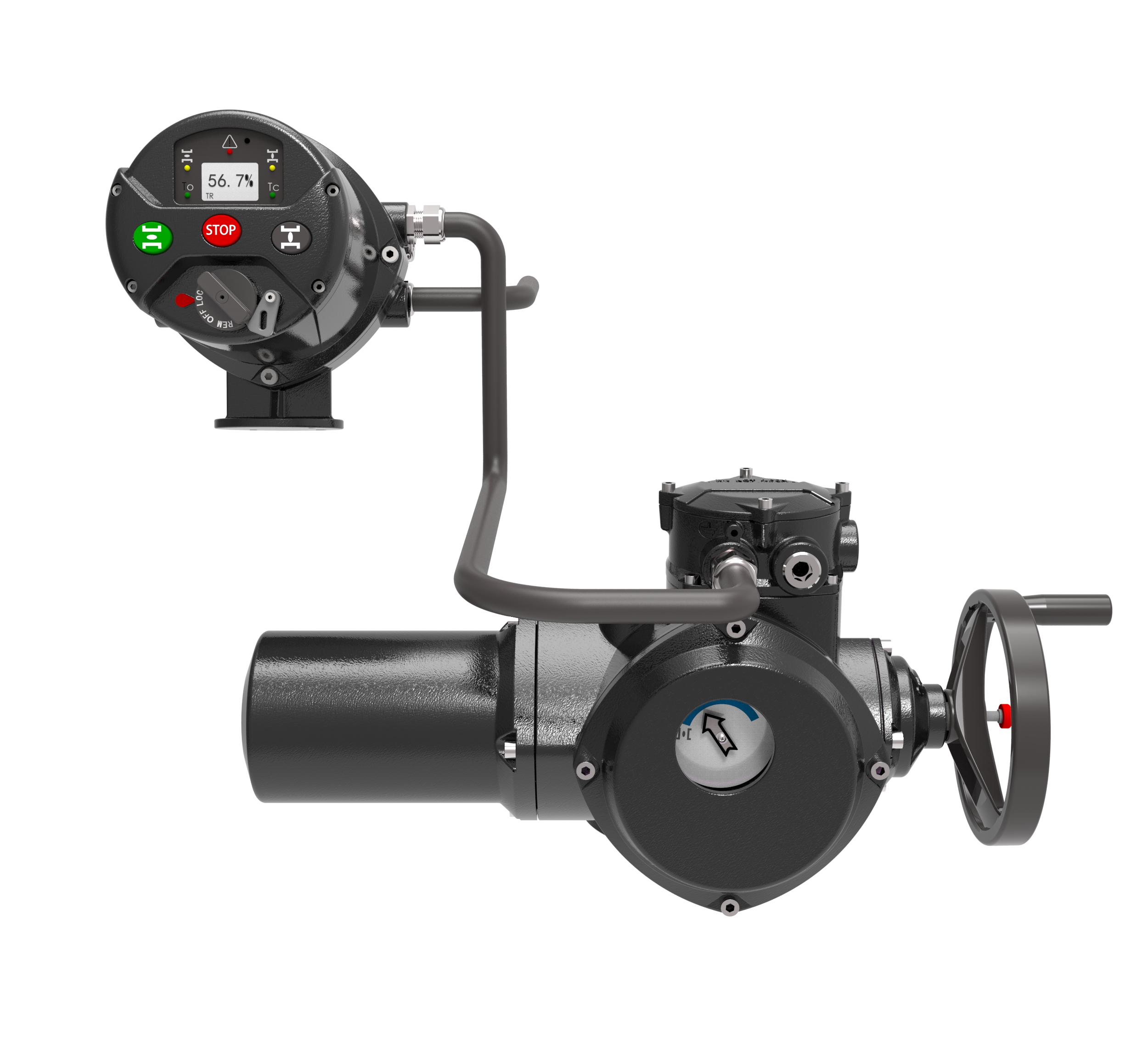
Clamp connection is a connection method that realizes quick disassembly and assembly of electric actuators and valves with the help of clamp components. The core advantage is that it can be quickly separated or combined without tools, and can ensure the hygienic cleanliness of the connection surface, making it the mainstream choice in industries with strict hygiene requirements such as food, pharmaceutical, and cosmetics.The core of clamp connection consists of three parts:
- Clamp Body: Usually made of stainless steel, which generates radial clamping force by tightening bolts.
- Sealing Element: Mostly use food-grade rubber or polytetrafluoroethylene sealing rings.
- Connection Interface: The connection end of the actuator and the valve needs to be processed into a "quick-fit joint" form to ensure that the clamp can fit closely.
- Sealing Logic: When the clamp is tightened, the radial force tightly presses the quick-fit joints of the actuator and the valve, squeezing the middle sealing ring to deform, thereby filling the gap and blocking the medium leakage channel.
- Applicable Scenarios
Hygienic Industries: Food, pharmaceutical, cosmetics and other fields with extremely high requirements for cleanliness, where valves need to be frequently disassembled for cleaning and sterilization.
Low-pressure quick-disassembly scenarios: Medium pressure ≤1.6MPa and scenarios requiring quick disassembly and assembly.
Small and medium-diameter valves: Suitable for diameters mostly DN15 - DN100, such as the connection between hygienic butterfly valves, ball valves and small electric actuators.
Low-pressure quick-disassembly scenarios: Medium pressure ≤1.6MPa and scenarios requiring quick disassembly and assembly.
Small and medium-diameter valves: Suitable for diameters mostly DN15 - DN100, such as the connection between hygienic butterfly valves, ball valves and small electric actuators.
- Key Selection Points
Match Joint Standards: Give priority to international general hygienic quick-fit joint standards.
Select Sealing Ring Materials: Select according to medium characteristics and hygiene requirements.
Limit Pressure and Temperature: Ordinary clamps are suitable for pressure ≤1.6MPa and temperature -20℃ ~ 150℃; if higher pressure or temperature is required, thickened clamps and high-temperature / high-pressure resistant sealing rings should be selected.
Select Sealing Ring Materials: Select according to medium characteristics and hygiene requirements.
Limit Pressure and Temperature: Ordinary clamps are suitable for pressure ≤1.6MPa and temperature -20℃ ~ 150℃; if higher pressure or temperature is required, thickened clamps and high-temperature / high-pressure resistant sealing rings should be selected.
2. Three Common Misunderstandings in the Connection Between Electric Actuators and Valves
Even if the correct connection method is selected, if the installation or matching is improper, it will still cause failures. The following are 3 types of high-frequency misunderstandings in the industry that need to be avoided:
- Misunderstanding 1: Ignore "Torque Matching" and Forcibly Use Small-sized Connections
Some engineers use small-sized flanges (such as F07) to connect large-torque valves (such as DN200 butterfly valves, which require F10 flanges) in order to save costs, resulting in overload of flange bolts. After long-term operation, bolts break, actuators fall off, and even valve stems bend.
Correct Approach: According to the rated torque of the actuator and the torque required by the valve, select the corresponding specification of the connection method (for example, if the torque ≥1000N・m, F12 and above flanges must be selected), and the rated bearing capacity of connection components (bolts, couplings) should have a safety margin of more than 1.2 times.
Correct Approach: According to the rated torque of the actuator and the torque required by the valve, select the corresponding specification of the connection method (for example, if the torque ≥1000N・m, F12 and above flanges must be selected), and the rated bearing capacity of connection components (bolts, couplings) should have a safety margin of more than 1.2 times.
- Misunderstanding 2: Eccentric Installation Leads to Increased Wear of the Shaft System
In the shaft sleeve or coupling connection, if the coaxiality deviation between the output shaft of the actuator and the valve stem exceeds the allowable range (such as the deviation of the elastic coupling > 0.6mm), it will cause shaft sleeve wear, coupling abnormal noise, and even overload and burnout of the actuator motor.
Correct Approach: Use a dial indicator to measure the coaxiality before installation to ensure that the radial deviation ≤0.4mm and the angular deviation ≤2°; when connecting flanges, use a level to adjust the levelness of the actuator and the valve to avoid uneven force on the flange surface.
Correct Approach: Use a dial indicator to measure the coaxiality before installation to ensure that the radial deviation ≤0.4mm and the angular deviation ≤2°; when connecting flanges, use a level to adjust the levelness of the actuator and the valve to avoid uneven force on the flange surface.
- Misunderstanding 3: Improper Selection of Sealing Accessories Causes Medium Leakage
When connecting flanges, if the gasket material does not match the working conditions, it will cause the gasket to age and fail, leading to medium leakage; when connecting shaft sleeves, if the set screws are not tightened or the material rusts, it will cause the shaft sleeve to slip.
Correct Approach: Select gaskets according to the medium temperature and corrosiveness; use stainless steel for set screws, tighten them with a torque wrench according to the specified torque after installation, and make anti-rust marks.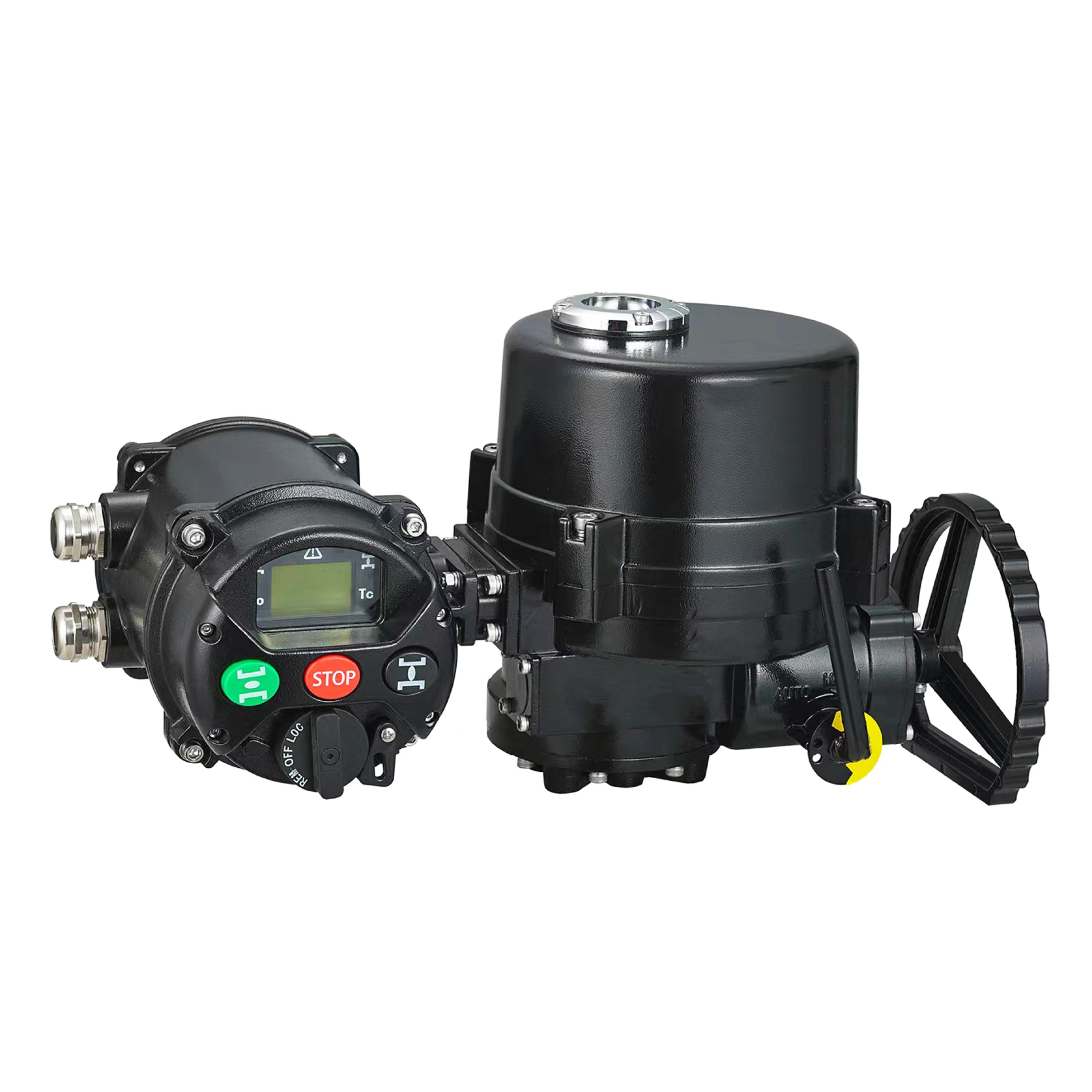
Correct Approach: Select gaskets according to the medium temperature and corrosiveness; use stainless steel for set screws, tighten them with a torque wrench according to the specified torque after installation, and make anti-rust marks.
3. Connection Type Quick Selection Table (Quick Matching Scenario)
To facilitate quick selection, the following table summarizes the core parameters and application scenarios of 4 connection types for direct comparative matching:
| Connection Type | Applicable Valve Diameter | Maximum Torque Resistance | Installation Difficulty | Maintenance and Repair Complexity | Core Application Scope |
|---|---|---|---|---|---|
| Flange Connection (ISO 5211) | DN50 - DN1000+ | ≤5000N·m | Medium | High | Industrial large-diameter valves, high-pressure working conditions |
| Clamp Connection | DN15 - DN80 | ≤5000N·m | Low | Medium | Small and medium-diameter valves, low-pressure quick installation |
| Magnetic Coupling Connection | DN25 - DN200 | ≤1500N·m | High | Medium | Different shaft centers, high-frequency oscillation |
| Welding Connection | Unlimited | No upper limit | High | Very Low | Extremely harsh environments, maintenance-free and no leakage |
Conclusion: Choosing the Right Connection Method is Key
The connection between an electric actuator and a valve is not a simple assembly process, but a comprehensive decision that must take into account the valve type, operating condition intensity, installation requirements, and maintenance needs. Whether it is the versatility of flange connections, the convenience of sleeve connections, the flexibility of coupling connections, or the sealing performance of welded connections, only by accurately matching the connection method to the specific scenario can failures caused by connection failure be avoided.
If you encounter special scenarios in specific projects, please provide parameters such as the valve DN (nominal diameter), torque requirements, and operating temperature. You are welcome to communicate with us via email by sending information to k.pan@athenavalve.com. Leveraging our 20 years of industry experience, we will provide you with customized connection solutions and technical support to help your fluid control system operate efficiently, safely, and stably.
If you encounter special scenarios in specific projects, please provide parameters such as the valve DN (nominal diameter), torque requirements, and operating temperature. You are welcome to communicate with us via email by sending information to k.pan@athenavalve.com. Leveraging our 20 years of industry experience, we will provide you with customized connection solutions and technical support to help your fluid control system operate efficiently, safely, and stably.
Top 15 Actuator Companies in the USA 2025
Difference Between Mechanical Life and Operational Life in Actuators
Related Article
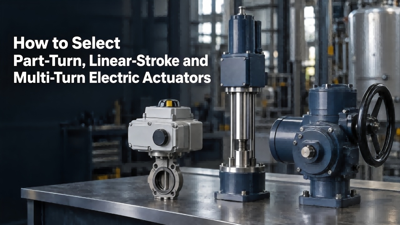
Learn differences among part‑turn, linear‑stroke and multi‑turn electric actuators. This guide covers matching valves, torque‑thrust calculation, 5‑step selection process and typical pitfalls for your industrial actuator applications.
How to Select Part‑Turn, Linear‑Stroke and Multi‑Turn Electric Actuators
Learn about electric actuator response speed, internal and external influencing factors and key selection points, to select suitable actuators for valve automation projects and ensure efficient and stable system operation.
Response Speed of Switch‑Type Electric Actuator
Valve Actuator Wiring describes wiring, commissioning and troubleshooting for electric valve actuators, guiding technicians to adopt standard wiring for stable industrial control.
Valve Actuator Wiring
Valen Tech explains electric valve actuator torque control and overload protection functions. Learn how multi‑turn & part‑turn actuators prevent jamming and mechanical damage for petroleum, chemical, power and water pipeline systems.
Introduction to Torque Control and Overload Protection Functions of Electric Valve Actuators