
What is a Butterfly Valve Actuator?
author: ATHENA GROUP
2026-10-28
During valve selection or replacement projects, many people ask: What exactly is a butterfly valve actuator? Simply put, it is a drive unit mounted on top of a butterfly valve that “rotates the valve automatically”. It converts electric, pneumatic or hydraulic power into a 0°‑90° rotary motion of the valve disc, enabling pipeline fluid to be opened, closed or flow‑regulated. As a brand specializing in fluid‑control actuators, Valen Tech has compiled the most‑frequently‑asked questions raised by engineers and purchasers into this article for a comprehensive explanation.
I. Relationship Between Butterfly Valve Actuator and Butterfly Valve
First, clarify the concepts. A butterfly valve is a compact, low‑resistance shut‑off valve whose core component is a rotatable circular disc that flips inside the pipeline like butterfly wings. A butterfly valve actuator is the power device that drives this disc to rotate.
Only when combined do they form a complete set of actuating equipment:
- Butterfly valve body: responsible for cutting off or regulating process media;
- Actuator: provides rotational torque and controls the rotation angle (typically 0°‑90°).
Butterfly valve actuators are almost indispensable for remote control, automatic control and frequent‑operation scenarios. This explains why they have become standard equipment in water treatment, HVAC, chemical, power‑generation and other industries.
II. How Does a Butterfly Valve Actuator Work?
Understanding the operating principle helps determine the required torque rating and power supply configuration.
The core logic follows the sequence: **power source → transmission mechanism → valve stem rotation → valve disc opening/closing**. Power from electricity, compressed air or hydraulic oil is converted into torque via reduction gears, pistons or yokes, turning the valve stem and flipping the disc. When the disc is parallel to the pipeline (0°), the valve is fully open; when perpendicular (90°), it is fully closed. Intermediate angles allow flow modulation. Operations can be performed manually or automatically via control signals from PLC, DCS and other control systems.
It should be specially noted that the torque required by a butterfly valve is not constant throughout its travel. Break‑to‑break torque peaks near the fully‑closed position. For modulating service, a dynamic torque spike occurs roughly between 30°‑70° opening, often exceeding the static seating torque. For this reason, actuators shall be selected according to the valve’s complete torque curve rather than relying solely on a single torque value from datasheets.
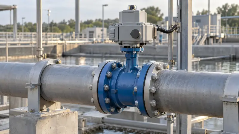
III. Main Types of Butterfly Valve Actuators
Based on power supply, there are four primary types, each suited for specific application scenarios:
1. Electric Butterfly Valve Actuator
Motor‑driven, featuring simple construction and precise control. Suitable for remote‑modulating and automated applications. Its greatest advantage is mains‑power supply compatibility with no compressed‑air source required. Widely deployed in water plants, pump stations and HVAC systems. Valen Tech’s VTEM series covers 100‑3,000 N·m with 18‑144 rpm, offering models for small‑to‑large‑size butterfly valves.
2. Pneumatic Butterfly Valve Actuator
Powered by compressed air. Delivers fast actuation, low cost and high reliability, ideal for frequent on‑off and quick‑start‑stop duties. Common variants include double‑acting types (air supply on both sides; valve position holds upon air loss) and spring‑return single‑acting types (automatically returns to fully‑open or fully‑closed safe position upon air loss for safety interlock applications).
3. Hydraulic Butterfly Valve Actuator
Driven by hydraulic oil. Capable of delivering high output torque, suited for large‑diameter, high‑pressure butterfly valves requiring substantial driving force, typically used in large‑scale water‑conservancy and heavy‑industrial conditions.
4. Manual / Worm‑Gear Actuator
Operated manually via handwheel or worm‑gear mechanism. Low‑cost option for infrequent operation with no automation requirements.
A frequent decision point lies between electric and pneumatic solutions: choose pneumatic if stable compressed‑air supply and fast on‑off action are needed; select electric for precise modulation and remote monitoring.
IV. Five Key Parameters for Correct Butterfly Valve Actuator Selection
Confirm these five points before purchasing to avoid common pitfalls:
1. Output Torque: Actuator output torque must exceed the maximum operating torque of the butterfly valve with adequate safety margin. For clean‑water and general‑industrial conditions, a safety factor of 1.3‑1.5 is recommended; for abrasive media or high‑cycle‑frequency service, adopt a factor of 1.7.
| Operating Condition | Recommended Safety Factor |
|---|---|
| Clean‑water and general‑industrial service | 1.3‑1.5 |
| Abrasive media or high‑frequency cycling | 1.7 |
> Note: Safety factors shall be calculated against the valve’s full torque curve. The actuator output torque under actual air‑supply pressure (or voltage) shall not exceed the Maximum Allowable Stem Torque (MAST) defined by ASME B16.34.
2. Power Supply: Confirm site supply voltage (220 V or 380 V), availability of compressed‑air supply and air‑pressure stability. This directly determines whether electric or pneumatic actuation is appropriate.
3. Control Mode: Confirm whether only on‑off operation is required, or continuous modulating control via 4‑20 mA signal is needed, together with required control signals and feedback functions.
4. Operating Environment: For outdoor, humid, high‑temperature, dusty or corrosive‑gas environments, select actuators with corresponding ingress‑protection ratings (e.g. IP67) and explosion‑proof ratings (e.g. Ex).
5. Fail‑safe Mode: Define whether the valve shall automatically open, automatically close or maintain its position upon loss of power or air supply. Pneumatic spring‑return units and electric actuators with backup power can satisfy safety‑interlock requirements.
Furthermore, mounting interfaces must not be overlooked. ISO 5211 specifies flange and drive connections between actuator and valve (F05‑F12 flange codes, square or double‑D drive). Mismatched interfaces are among the most‑frequent on‑site installation faults: bolts may fasten, yet stem square drive, flange diameter or bracket height fail to align. Always cross‑check against valve drawings before procurement.
Manufacturer recommendation: Prioritize manufacturers with transparent torque‑curve data, available certification documents and application‑selection support. The Valen Tech technical team can provide torque calculation and application‑selection support upon request, delivering matched torque and configuration suggestions to reduce risks of self‑calculation errors.
V. Typical Application Sectors for Butterfly Valve Actuators
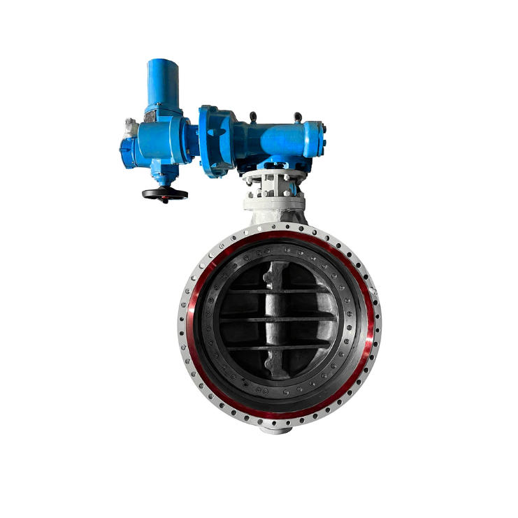
- Water Treatment & Municipal Water Supply: Pump outlets, chemical‑dosing systems, inlet/outlet for clean‑water tanks; electric actuators are widely adopted.
- Heating, Ventilation and Air‑Conditioning (HVAC): Modulation for chilled‑water and cooling‑water pipelines.
- Chemical & Petrochemical Industries: Corrosive‑media service and emergency shut‑off; pneumatic plus explosion‑proof configurations are common.
- Power Generation & Energy: Large‑diameter pipelines for circulating‑water and ash‑removal systems.
- Food & Pharmaceutical Industries: Sanitary and easy‑to‑clean requirements, frequently paired with stainless‑steel butterfly valves and electric actuators.
## VI. Frequently Asked Questions (FAQ)
Q1: What to do when a butterfly valve actuator jams?
Cut off power or air supply first. Inspect for mechanical faults including foreign objects trapped against the disc, corroded valve stems and worn gears. If mechanical components are intact, verify whether insufficient torque was specified. Many “jamming” incidents stem from inadequate safety margin, where dynamic torque spikes stall the actuator.
Cut off power or air supply first. Inspect for mechanical faults including foreign objects trapped against the disc, corroded valve stems and worn gears. If mechanical components are intact, verify whether insufficient torque was specified. Many “jamming” incidents stem from inadequate safety margin, where dynamic torque spikes stall the actuator.
Q2: How often shall electric actuators be maintained?
Inspections are generally required every 6‑12 months, covering lubrication, terminal‑tightness checks, insulation testing and stroke calibration.
Inspections are generally required every 6‑12 months, covering lubrication, terminal‑tightness checks, insulation testing and stroke calibration.
Q3: Can a pneumatic actuator replace an electric actuator?
It depends on working conditions. Pneumatic solutions apply when compressed‑air is available and fast shut‑off is required. Electric actuators are preferred for precise modulation or sites without air supply. The two cannot be simply substituted for each other.
It depends on working conditions. Pneumatic solutions apply when compressed‑air is available and fast shut‑off is required. Electric actuators are preferred for precise modulation or sites without air supply. The two cannot be simply substituted for each other.
VII. Summary
Butterfly valve actuators are indispensable actuation devices for automated fluid‑control systems. Selection hinges on five core dimensions: torque, power source, control mode, environmental protection rating and fail‑safe mode. Apply sufficient safety margin derived from the complete valve torque curve and verify mounting interfaces against ISO 5211. Mastering these points minimizes missteps for both new‑project specification and legacy‑equipment replacement. Valen Tech is an actuator brand under Italy’s Athena Group, manufacturing part‑turn electric actuators and yoke‑type pneumatic actuators, backed by up to 18‑month warranty. Torque calculation and application‑selection support are available for your projects upon request.
How to Select Part‑Turn, Linear‑Stroke and Multi‑Turn Electric Actuators
Related Article
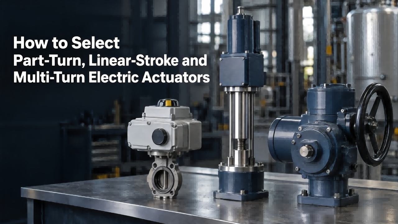
Learn differences among part‑turn, linear‑stroke and multi‑turn electric actuators. This guide covers matching valves, torque‑thrust calculation, 5‑step selection process and typical pitfalls for your industrial actuator applications.
How to Select Part‑Turn, Linear‑Stroke and Multi‑Turn Electric Actuators
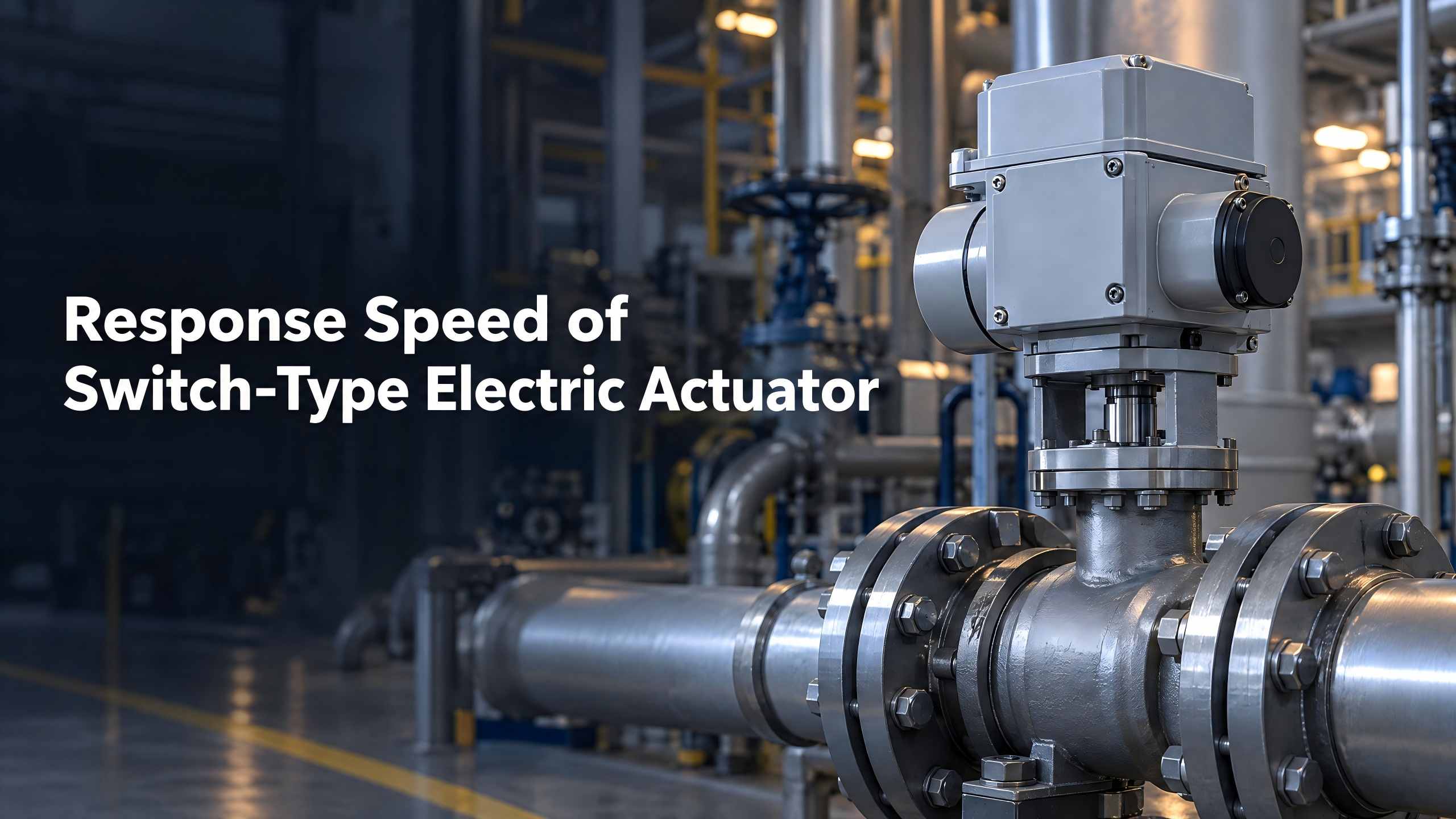
Learn about electric actuator response speed, internal and external influencing factors and key selection points, to select suitable actuators for valve automation projects and ensure efficient and stable system operation.
Response Speed of Switch‑Type Electric Actuator
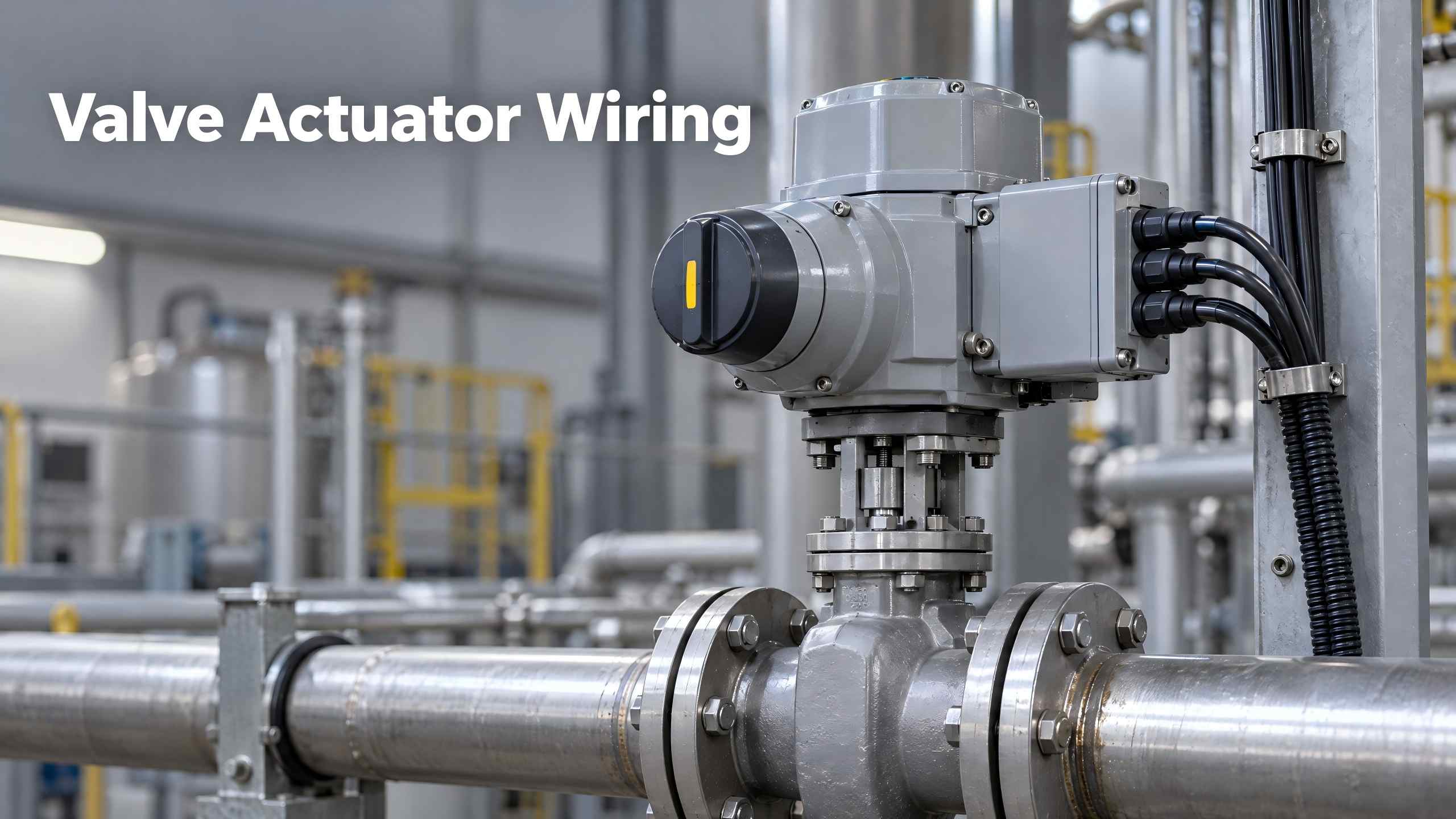
Valve Actuator Wiring describes wiring, commissioning and troubleshooting for electric valve actuators, guiding technicians to adopt standard wiring for stable industrial control.
Valve Actuator Wiring
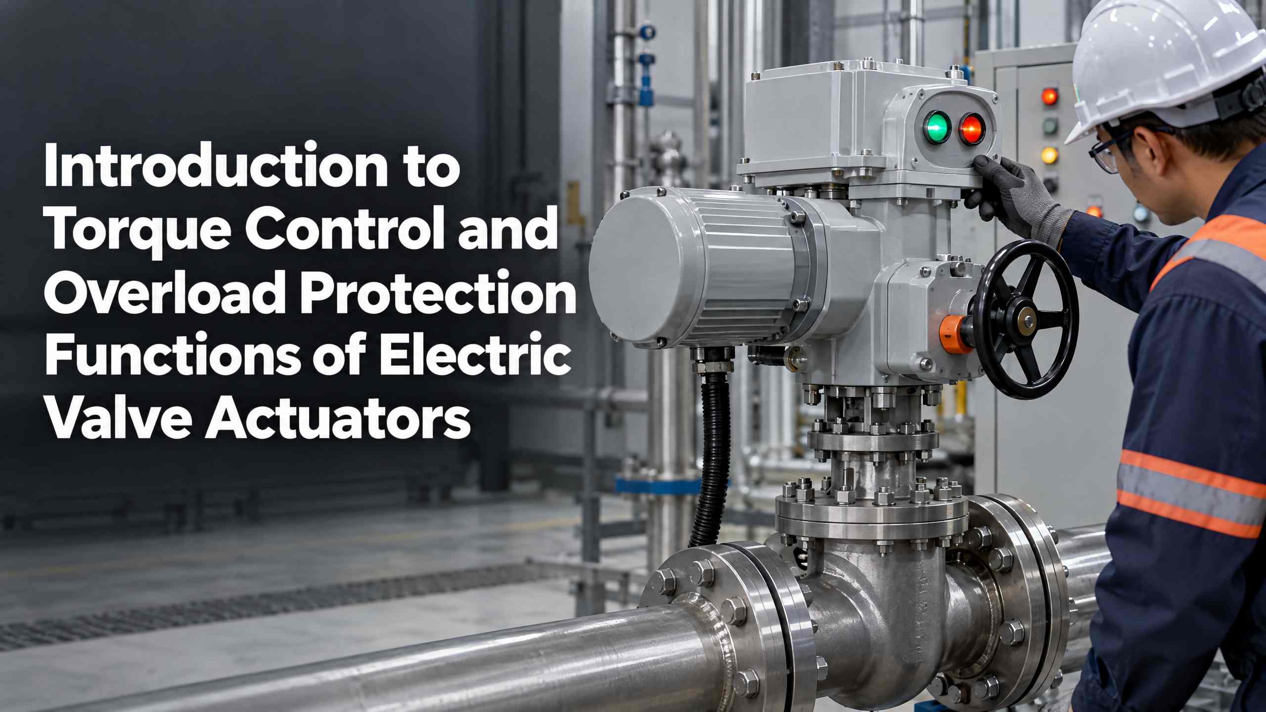
Valen Tech explains electric valve actuator torque control and overload protection functions. Learn how multi‑turn & part‑turn actuators prevent jamming and mechanical damage for petroleum, chemical, power and water pipeline systems.
Introduction to Torque Control and Overload Protection Functions of Electric Valve Actuators